Ok, so I just went back and looked at the hd44780 code for pin i/o control and saw something that I had forgotten about.
I no longer use the LiquidCrystal library so I often forget about some of the issues in that code that have been fixed in the hd44780 library code.
There can be a timing issue with the LiquidCrystal library when trying to use 3v Arduino boards with a 5v LCD.
When using the 3v modules like the ESP32 and the esp8266 there can be and often is a timing issue on the E signal transitions due to the slew rate of the rising E signal.
It is subtle but here is what is happening.
Since the 3V voltage is right on the edge of working with the 5V LCD, to ensure that the signals are high enough voltage for the LCD, the code must wait just a tiny bit more to allow the signals to fully rise all the way up to the full 3V voltage.
If you don't do this, communication with the LCD can be unreliable.
How bad this is, or whether it shows up depends on the board, the supply voltages, and the wiring used to connect between the board and the LCD.
The hd44780 library has code to work around all this so it should not be an issue.
My suggestion is to install the hd44780 library and switch over to using the hd44780_pinIO i/o class.
hd44780 is available in the IDE library manager so you can quickly install it.
You should only have to change 3 lines of code in your sketch.
2 lines for the header files to include and the line for the constructor object.
The constructor arguments are compatible with the LiquidCrystal constructor so all the arguments are the same.
The hd44780 library has many additional features and is also faster than the LiquidCrystal library.
See the included Documentation for links to all the documenation.
The main github page is here:
I would recommend that you try the library and try the LineWrap sketch to make sure it is working on all 4 lines.
arpruss:
In 2-line mode, usually I just get all black rectangles on lines 1 and 3 (again, I can dim them until they are barely visible, and text never shows up, so I don't think it's a contrast issue) and nothing on lines 2 and 4.
And there you have it. That is the complete answer.
Black rectangles on lines 1 and 3 is explicitly telling you the contrast is set correctly (because you are seeing the blocks) and the HD44780 is not responding to your code (because they are just blocks).
Bill has explained why.
And yes, you could make it work by turning it into the 3 V version of the display. Rather than mounting the ICL7660 on the vacant position on the board with its two capacitors and resetting the jumpers, you could just supply it from 3.3 V and provide a negative 1.7 V supply via the variable contrast resistor, to pin 3. Or a more negative voltage (-5V?) with a larger resistor value (a 10k variable).
Thanks for the lead about hd44780 library. I am getting some rather interesting results:
hd44780 library + begin(20,4) + 5V LCD supply: black squares on lines 1 and 3; nothing on lines 2 and 4
hd44780 library + begin(20,4) + 3.3V LCD supply: correct display on all four lines (yay!), but extremely low contrast (even when grounding contrast pin)
hd44780 library + begin(20,1) + 3.3V LCD supply: correct display on line 1, but extremely low contrast
LiquidCrystal library + begin(20,1) + 3.3V LCD supply: correct display on line 1, and very good contrast.
I don't understand why the hd44780 library gives much worse contrast than the LiquidCrystal library in one-line mode.
Not sure what is going on with the difference in contrast between hd44780 vs LiquidCrystal.
However, for this kind of testing, you really need to power off everything to make sure things are starting from a common state to ensure valid results.
The reason is it could be that some of the initialization may be failing and so the LCD may be still in an initialization state from the previous test vs being initialized by the current test.
The initialization in LiquidCrystal is different.
It will initialize the LCD to 1 line mode in the constructor before begin() is called.
This should not make any difference.
What code were you running?
What about the hd44780 hd44780_pinIO examples.
Are they working correctly? especially the LineWrap example.
I am now very curious about these results, particularly on the hd44780 library, and would like to work through this to figure out exactly what is happening.
Please post a link to the actual 20x4 that you have bought e.g. Ebay Sale page.
If you can't find the exact page, compare your pcb with other items on Ebay, Ali, ...
If you can't find the exact pcb, please post a photo of your pcb. And post a photo of your actual wiring to the ESP32.
We are on post #24 after seven whole days !!
Ok, most 20x4 are the same. So readers expect you to have a standard 20x4.
If we had a link to your actual hardware in #0, you probably would have been solved by bperrybap and floresta within a few hours. Possibly minutes if you are in the same timezone as them.
Links cost you a few seconds from your life. They save days of heartbreak.
Post some photos so we can see how you have everything wired up.
The photos need to be good enough and clear enough so that we can see everything well enough to replicate your setup.
and also a photo of your soldering on the LCD so we can also take a look at soldering for the wires and/or header attached to the LCD.
I think I've figured out why things were different with hd44780 and LiquidCrystal in 1-line mode. In my setup, the hd44780 library fails to set 1-line mode. One way to test it is this code:
If 1-line mode is set correctly by the library (which it should be, since I'm calling lcd.begin(20,1)), only two of the four display lines should be filled. But if 2-line mode is set, then all four display lines are filled (because we're filling up all of the display RAM). With the hd44780 library, I am seeing all four display lines (but with very low contrast). With the LiquidCrystal library, only two lines are filled (with high contrast).
I also found a way to fix this. In hd44780.cpp, in hd44780::begin(), insert a delay(1) right before
command(HD44780_FUNCTIONSET | _displayfunction);
With the delay inserted, lcd.mode(20,1) correctly sets 1-line mode (two lines filled, with high contrast) and lcd.mode(20,4) correctly sets 2-line mode (four lines filled, with low contrast).
I don't know if adding this delay(1) would help with other hardware setups. I recommend some testing.
Interesting. Good find!
You found a serious timing bug in the hd44780 library. I guess I hadn't tried 1 line mode with pin i/o control on a fast processor in quite some time. (like several years)
Lately I mostly use i2c backpacks, and while I do test pin i/o on pic32, esp8266, and esp32, I test it using a 16x2 shield.
I guess I need to add a test case to test 1 line mode with pin i/o control on a fast processor to my test cases for each library release.
Based on the issue, I'm not sure why it had an issue setting 1 line mode.
If there is a timing issue, It should have a problem setting 2 line mode rather setting 1 line mode.
i.e. the function set command to set the number of lines and the font would fail / be ignored if it was sent too quickly.
While adding the 1ms delay can "fix" it, I will likely not choose to fix that way.
The issue is that the code in begin() is directly calling the low level iowrite() i/o class function to do the 4 bit initialization commands. This code is not setting the internal start of the instruction time by calling markStart(_insExecTime);
And then when command() is called a bit later to do the function set to set the number of lines and font, the i/o class code, pinIO, in this case, will call waitReady() but waitReady() will not delay any time since the code that called iowrite() set the LCD to 4 bit mode never marked the time when the command was sent
waitReady() will think that more than enough time has elapsed to finish the previous command even if zero time has elapsed.
If you send commands too quickly to the LCD, it typically silently ignores them and that is what is happening.
I'll get that fixed and push out a new hd44780 library version within a couple of days.
In terms of contrast, as we said before you will see a significant contrast difference between 1 line mode and 2 line mode with the same voltage on the Vo pin.
That is normal since 1 line mode has twice the duty cycle so it dramatically affects the contrast.
So when you added the delay() and run the LCD at 5v is everything now working properly?
bperrybap:
Based on the issue, I'm not sure why it had an issue setting 1 line mode.
Could it be that my LCD is by default in 2-line mode? Here is some evidence of that: When I comment out command(HD44780_FUNCTIONSET | _displayfunction) in the hd44780 library or command(LCD_FUNCTIONSET | _displayfunction) in the LiquidCrystal library, I get 2-line mode (with low contrast).
Here is some further evidence that it's by default in 2-line mode. If I start test code on the ESP32 with the LiquidCrystal library (for some reason this experiment doesn't work with the HD44780 library) with the LCD unpowered, and then I power up at the LCD at 3.3V, all four display lines still work (with low contrast), despite the init code not having been run, except for an off-by-one error with cursor positioning. So with no init code, it's in 4-line mode.
bperrybap:
In terms of contrast, as we said before you will see a significant contrast difference between 1 line mode and 2 line mode with the same voltage on the Vo pin.
That is normal since 1 line mode has twice the duty cycle so it dramatically affects the contrast.
So when you added the delay() and run the LCD at 5v is everything now working properly?
The duty cycle explanation makes a lot of sense.
Sadly, at 5V it still doesn't work for me: I get black squares in lines 1 and 3 despite lcd.begin(20,4).
Here's another 5V experiment. With the LiquidCrystal library, with lcd.begin(20,4), I normally get black squares in lines 1 and 3. But if I start up the ESP32 before powering up the LCD, so that the library init code is run before the LCD is powered up, then I get an almost working 4-line display, at good contrast, except that the display coordinates are off by 1: when I do setCursor(0,0) it actually puts the cursor at (1,0). I can fix the off-by-one issue by issuing lcd.command(0x28) in the display loop. Oddly, this doesn't work with the HD44780 library.
Please post a link to the actual 20x4 that you have bought e.g. Ebay Sale page.
If you can't find the exact page, compare your pcb with other items on Ebay, Ali, ...
If you can't find the exact pcb, please post a photo of your pcb. And post a photo of your actual wiring to the ESP32.
Please post some photos of your setup.
Post some photos so we can see how you have everything wired up.
The photos need to be good enough and clear enough so that we can see everything well enough to replicate your setup.
and also a photo of your soldering on the LCD so we can also take a look at soldering for the wires and/or header attached to the LCD.
--- bill
Seriously. 1 or 2 minutes from your life. This interesting problem could be resolved for you.
More importantly, it might help anyone that happens to have your unusual hardware.
It would be hard to photograph it in such a way that one can tell what wire goes where: it's too much of a mess of wires hanging in the air, as I am connecting the LCD via Dupont connectors to the ESP32.
Its been a week and you are still having issues getting a lcd up and working.
You are all over the place trying this, trying that but not really doing what we are asking.
People have been asking since the very first response for information that you not providing.
Please slow down (stop) and provide the information that we are asking for in order for us to be able to help you.
arpruss:
It would be hard to photograph it in such a way that one can tell what wire goes where: it's too much of a mess of wires hanging in the air, as I am connecting the LCD via Dupont connectors to the ESP32.
A "mess of wires" may very likely be your issue as poor wiring can cause all sorts of weird issues.
Wiring issues is the #1 cause of LCD issues. Either incorrect wiring, issues with soldering, or issues with the connections either inside the actual wire or where the wires connect to something.
There can also be issues when wires are a bit long or from getting cross talk between them.
There are also several kind of issues that can come up when breadboards are used.
This is why we need to see actual photos of what you are using.
I'll wait for photos that provide the information that David and I asked for before any further comments.
See post #29 for summary of what we are wanting.
--- bill
There are issues that need to be resolved and all this experimentation is not really helping.
Known items:
LiquidCrystal library won't work reliably with a 3v esp part without modifications when LCD is running at 5v
hd44780 has a timing issue in begin() that must be fixed (you worked around this this with the delay(1))
the LCD should be run at 5v to ensure contrast works properly
needed voltage on Vo for good contrast will vary depending on supply voltage and LCD 1 line vs 2 line mode
(The actual LCD only has 2 modes, 1 line and 2 line, 2 line mode is set by the library whenever it is told there is more than 1 line)
Again this is how I would recommend that LCD should be connected and used to get it working:
patch the hd44780.cpp code to add the delay(1) as you previously described
tell the library the LCD is 20x4 (no matter how many of those 4 lines you are actually using)
run the LCD at 5v
set the contrast voltage appropriately for a good contrast using a pot with wiper to Vo and 1 leg to gnd.
(other leg of pot not connected to anything)
If there are issues when using it this way, it is likely a wiring or soldering issue.
But for now, get us some photos so we can see what you have wired up and see what your soldering looks like.
Be more specific. e.g.
U1 - U5 in the same positions.
R1-R5, RF, R8, R9 in the same positions
C1, C2 in the same positions
J1, J2 in the same positions
R6, R7, C3, C4, U6 not mounted.
all the copper traces look similar.
I am no good at taking photographs. But it was fairly simple to compare the components in your link.
And not too difficult to type the text.
As I said earlier, a few minutes of your time might get a solution from Bill and Don.
You can even say : my soldered joints are 100% or all Duponts are new.
With the LCD VCC pin connected directly to the 5V pin on the ESP32, I get black squares in 2-line mode with both libraries.
When I put a diode between the ESP32 5V pin and the LCD VCC pin, everything works great in 2-line mode with both libraries: 4 lines of display, good contrast (with contrast pin grounded), complete success.
Here's my guess as to why the diode makes a difference. The ESP32 5V pin normally was supplying about 4.6V to the LCD. I am guessing that the data levels of the HD44780 are pegged to the supply voltage, and the 3.3V data from the ESP32 was insufficient to control the HD44780. However, the diode dropped the supply voltage to 4.0V. With the supply voltage at 4.0V, the 3.3V data from the ESP32 was sufficient to control the LCD.
If I am right, then what I needed was a sweet spot in the LCD VCC. When the LCD VCC was too low (e.g., 3.3V) then I needed a negative voltage for correct contrast. When the LCD VCC was too high (e.g., 4.6V or higher) then I needed a data level higher than what the ESP32 produces. But there is a sweet spot in the supply voltage where the 3.3V data level is good enough and the contrast works without negative voltage.
And another bonus of the diode. Without the diode, serial uploads to the ESP32 would fail until I unplugged the LCD from 5V (they worked fine with the LCD at 3.3V). But with the diode in place, serial uploads work fine.
So it's looking like this is a complete solution, though it is rather hackish. Do my speculations sound reasonable? I am much more of a software than a hardware guy.
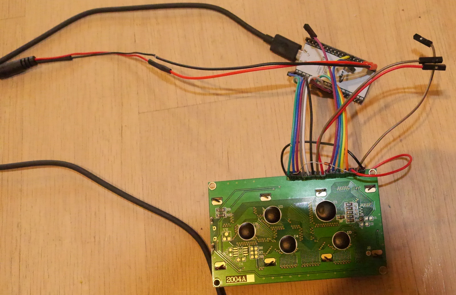
And here's a picture of the horrible looking prototype. You can see the diode pressure fitted into the backs of two Duponts.
The barrel plug (on the left, partly out of frame) is to connect to our exercise bike's rotation sensor. The project is a Bluetooth adapter for our exercise bike so it can be used with Zwift or RGT Cycling, but as a bonus I am adding a display with better data than the bike's built-in computer has. (The really hard part of the project is the physics calculations to get the wattage from the resistance setting and the rotation speed, since of course the bike manufacturer has not published speed / power curves. I've been figuring out the resistance quantities by attaching a known weight to the pedals and measuring drop times.)
The hd44780 library has been updated and a new version (1.3.2) has been published and should be available in the library manager in an hour or so.
Notable fixes:
fixed timing issue in begin() on VERY fast processors like ESP using pinIO
fixes to hd44780_NTCU165ECPB i/o class for SPI and s/w SPI for esp32
on a related note. These issues cropped up because the esp32 is so fast.
There were some potential timing issues that had just never cropped up yet.
the esp32 can toggle a pin using DigitalWrite() in about 80-100ns
This can even cause things like bit banging spy using shiftOut() to fail from being too fast, which is what happened to the NTCU165ECPB i/o class.
I just looked at the data sheet, and it says that the HD44780U high data level has a minimum of 0.7VCC. At 4.68V from the ESP32's "5V" pin, that would be 3.28V. I just measured the output of GPIO12 (connected to RS) at around 3.22V, which isn't enough. But when I lower the VCC via the diode to 4.08V, the minimum high data level becomes 2.86V, which works much better. So I think my guess as to what was going on was correct.
Still waiting for the information we asked for.....
I know I said I wouldn't comment further until we received the information we asked for but here is one last comment before I drop out of this thread.
arpruss:
So I think my guess as to what was going on was correct.
I'm not convinced.
So far in playing around with MANY glcds & lcds and over more than 10 years of being involved with and even writing various Arduino GLCD and LCD libraries, I've not had an issue of a 5v part seeing a 3v high output as a high input.
And that is using several different 3v processors, pic32, esp8266, esp32, arm cortex M0, arm cortex M4.
And this for both direct pin control and i2c signals.
Yes I've seen a few issues related to slew rate timing, but those have been dealt with in the hd44780 library code.
btw,
here is some additional information about using 3v outputs with 5v inputs that you might find useful.
Is the HD44780 a CMOS or a TTL part? The link you give says that for 5V CMOS, things are undefined for inputs between 1.5V to 3.5V. And the 3.5V precisely matches the data sheet's 0.7*VCC figure.
I, too, have never had trouble before with a 5V part registering 3V inputs. But it's hard to see why else dropping the supply voltage makes the LCD work great.
Anyway, I have a fully working solution now, so I'm happy. Thanks everyone for your patience!