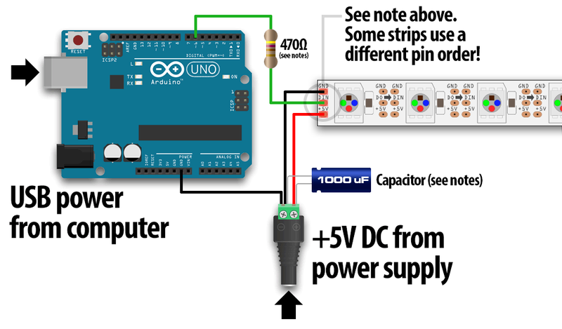
I got some 2812 LED strip and have been experimenting with it on a UNO board. I am using pin 6 for the data with a 470 ohm resistor. The LED strip works on UNO board but when I put a Nano in it's place the strip will not light. Same sketch, same wiring. The sketch uploads fine and I even changed the data pin once to 13 so I could see the onboard LED blink to verify I was transmitting data, nothing. I am using a external 5V supply to power the strip and the boards. What am I missing???
What is missing is your code and a wiring diagram.
How are you powering the LED strip? Not from the Nano, I hope...
Barn-E-Stormer:
I am using a external 5V supply to power the strip and the boards.
The code works fine on UNO board but does not work on the Nano. Is there a difference in the boards that would make the code not work? I thought they were interchangeable?
As for a schematic....+5v to +5v pin, ground to ground and pin 6 for data.
Barn-E-Stormer:
The code works fine on UNO board but does not work on the Nano. Is there a difference in the boards that would make the code not work? I thought they were interchangeable?
As for a schematic....+5v to +5v pin, ground to ground and pin 6 for data.
You said that already. There are hardware differences. One is that the voltage regulator on the Nano has a lower current rating. So the problem is probably as I implied before... you are overloading that regulator. Put your finger on it (careful not to burn yourself).
You have to tell us how you are powering the circuit, Vin or USB or 5V. We asked you about it in reply #1, you never responded. That can be a turn off for many helpers.
How much current does the strip or strips draw when turned on? Are you using a transistor to switch the strip(s) on or just trying to sink the current with the Nano?
BTW, led strips normally implies multiple led's per strip, probably to the point that the Nano I/O pin might not be able to drive the strip.
Go back to basics with the Nano, load a simple led blink program and see if that works.
It would still be very helpful for anyone trying to help you if you would provide the code and a circuit diagram so that we don't have to waste time pulling necessary details from you. With your code in hand we can load it onto a Nano of our own and be able to see what happens.
#include "FastLED.h"
#define NUM_LEDS 300
CRGB leds[NUM_LEDS];
#define PIN 6

void setup()
{
  FastLED.addLeds<WS2811, PIN, GRB>(leds, NUM_LEDS).setCorrection( TypicalLEDStrip );
}

// *** REPLACE FROM HERE ***

void loop() {
  rainbowCycle(20);
}

void rainbowCycle(int SpeedDelay) {
  byte *c;
  uint16_t i, j;

  for(j=0; j<256*5; j++) { // 5 cycles of all colors on wheel
    for(i=0; i< NUM_LEDS; i++) {
      c=Wheel(((i * 256 / NUM_LEDS) + j) & 255);
      setPixel(i, *c, *(c+1), *(c+2));
    }
    showStrip();
    delay(SpeedDelay);
  }
}

byte * Wheel(byte WheelPos) {
  static byte c[3];

  if(WheelPos < 85) {
   c[0]=WheelPos * 3;
   c[1]=255 - WheelPos * 3;
   c[2]=0;
  } else if(WheelPos < 170) {
   WheelPos -= 85;
   c[0]=255 - WheelPos * 3;
   c[1]=0;
   c[2]=WheelPos * 3;
  } else {
   WheelPos -= 170;
   c[0]=0;
   c[1]=WheelPos * 3;
   c[2]=255 - WheelPos * 3;
  }

  return c;
}


// *** REPLACE TO HERE ***

void showStrip() {
 #ifdef ADAFRUIT_NEOPIXEL_H
   // NeoPixel
   strip.show();
 #endif
 #ifndef ADAFRUIT_NEOPIXEL_H
   // FastLED
   FastLED.show();
 #endif
}

void setPixel(int Pixel, byte red, byte green, byte blue) {
 #ifdef ADAFRUIT_NEOPIXEL_H
   // NeoPixel
   strip.setPixelColor(Pixel, strip.Color(red, green, blue));
 #endif
 #ifndef ADAFRUIT_NEOPIXEL_H
   // FastLED
   leds[Pixel].r = red;
   leds[Pixel].g = green;
   leds[Pixel].b = blue;
 #endif
}

void setAll(byte red, byte green, byte blue) {
  for(int i = 0; i < NUM_LEDS; i++ ) {
    setPixel(i, red, green, blue);
  }
  showStrip();
}
I got this code from a example. It and all the other FastLED examples work on the Uno board. When I switch the Uno for the Nano, using the same pins (it's a only a 3 pin schematic, 5V+Ground+Data) I get nothing on the strip.
I thought maybe the Nano doesn't need the resistor on the data line?