For background here I'm using a 3.3V Arduino pro mini.
I recently came across a little module that I need to control, and it has a power up sequence where I must ground a pin on the module for >1s.
My idea was to try-state an Arduino pin, and then use it as a sink when I need to power-up the module.
The problem is that the module's power logic gate is internally pulled up to the battery (4.2V), and I'm worried this may negatively effect the Arduino's pin.
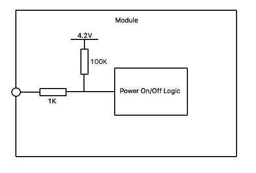
The module's datasheet states that the power pin is internally pulled up to 4.2V via a 100K resistor, and that there's also a 1K resistor between the logic gate, and the power pin input. (diagram 1)
So, I was hoping to bounce a few ideas off everyone here.
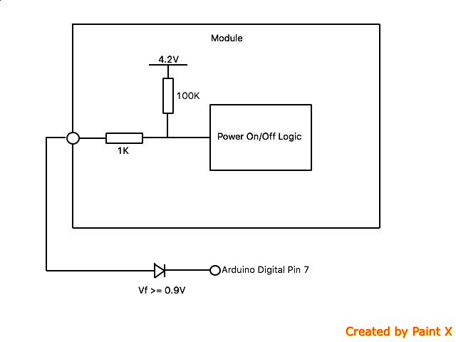
Obviously, attaching the pin directly to the arduino is not the best solution. But would it create a problem? (diagram 2)
It's going to usually be left in the tri-state.
Would putting a diode in between the power pin and the arduino pin solve this? (diagram 3)
The forward voltage drop should not allow any quiescent current to flow while the pin is try-stated. When I ground the pin, current should flow to ground, correct?
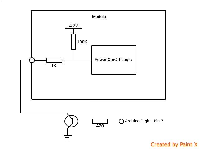
Obviously a transistor + resistor (diagram 4), is the best way to fix this; however, board space being at premium, I was hoping to take option 2.
Connecting the Arduino Vcc input, on the board side pins Only to the 4.2 V device power (possibly a LiPo cell for power?) would by far be the simplest method as there is no DC level shifting required...
A diode that prevents 4.2V from flowing into the 3.3V pin will also prevent 4.2V from flowing into that pin when it's at 0V.
It depends where you put the diode, I had not considered that anyone could miss read the comments so let me say that this diode would be a clamping diode to the 3V3 supply not inline with the signal.