Hi everyone, I was hoping someone could shed some light on an issue of mine. So I have a 3.3v regulator which steps down the voltage anywhere from 12v to 5v. I tested the chip on a solderless breadboard by its self and worked great (checked voltage with DMM). However when I soldered it onto my full project, it doesnt output 3.3v, when supplied with 12v it outputs around 6v, and if supplied with 5v it outputs 2.5v ish. Does anyone have any idea as to why this is?
The schematic is attached below.
Thanks in advance.
Dean.

Did you try replacing the regulator?
Not yet cause its soldered to the board now
What is the 3.3 volt regulator part number and what does the data sheet say (if anything) about capacitors on the input and output ?
Specification:
Icstation super mini AMS1117-3.3 DC-DC step down voltage converter module
Support DC 4.75-12V input and 3.3V fixed voltage and 0.8A current output
3 pins pinout can be easy to connected with your MCU development and provide the contant power supply.
Module Size: 12.33 X 8.6mm/0.49 X 0.34inch
And this is the link where i bought them
My past use of those modules has shown me they are junk. Out of 10 regulators (I tried both their 5V and their 3.3V versions) the only one I got left that may still work is the one I did not try to use in a circuit.
Fair enough, just it worked perfect on the solderless breadboard when i tested it before i sokdered it to the board.
Would devices that operate on 3.3v such as bluetooth module work fine on 2.5 or is it to far apart?
If these ones are garbage is there another product you would recommend to change either 5v or 12v down to 3.3v?
Thanks in advance.
So far the ESP32's have not been blowing thse up
3.3V regulator that has worked out well. You'll needs to add input and output filtering caps.
Hi,
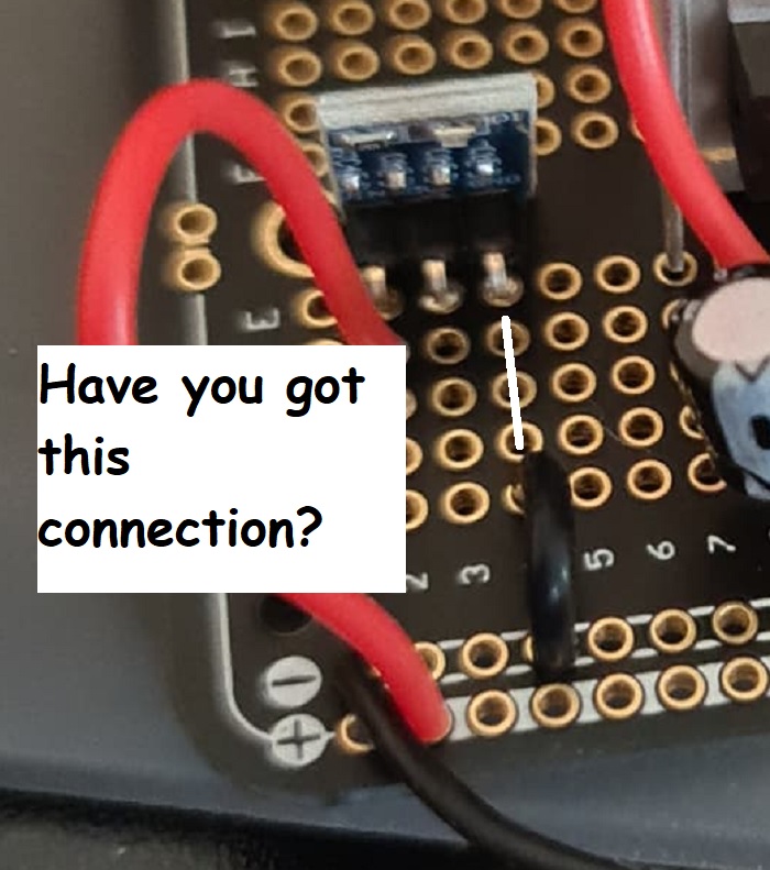
What voltage do you measure between your PCB gnd and the gnd pin of the regulator board.
It sounds like you have no gnd connection to the gnd pin of the regulator.
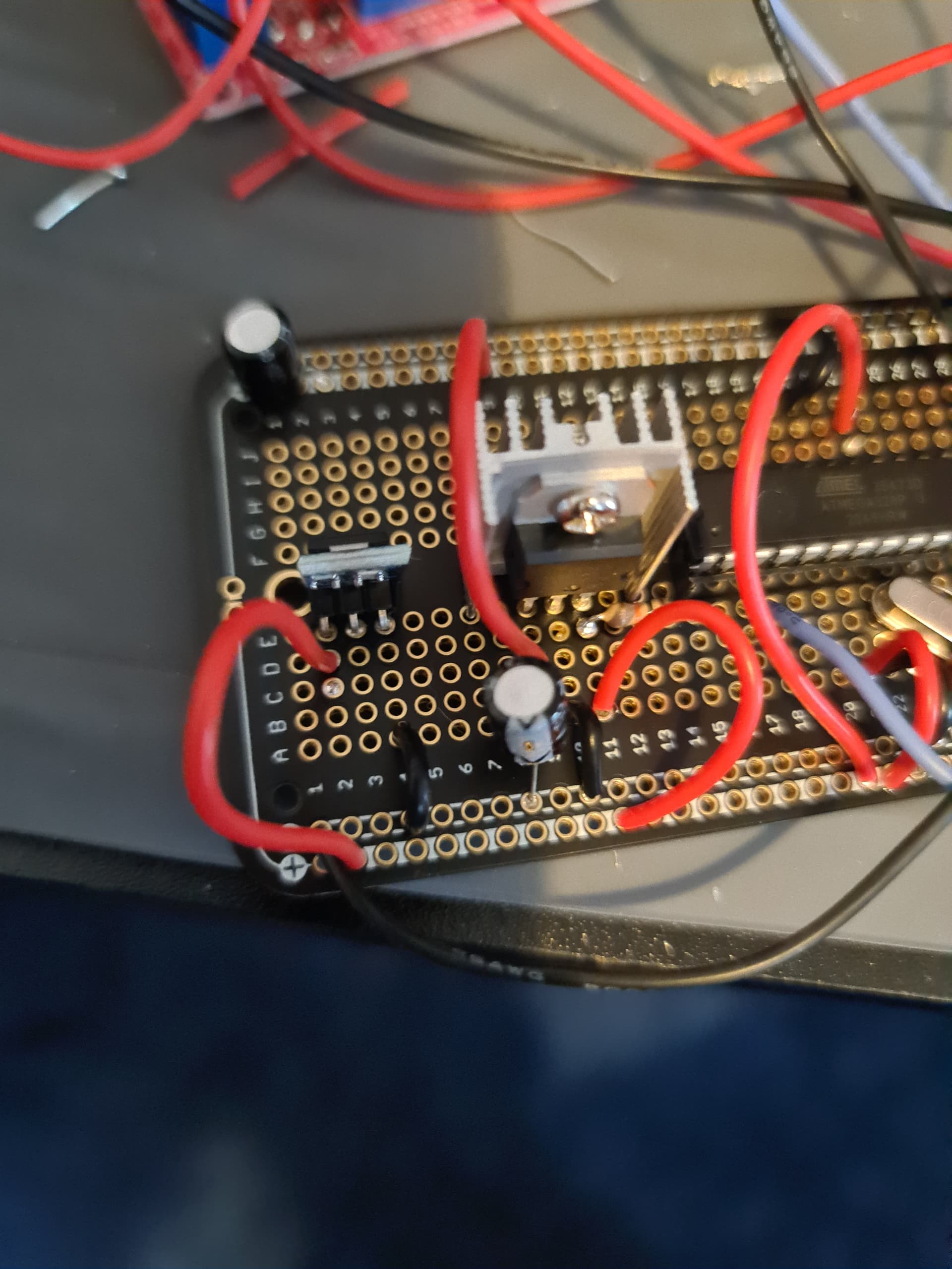
Can you please post a picture of your project so we can see your component layout?
Thanks.. Tom... ![]()
![]()
![]()
![]()
I have two voltage rails one 12v and one 5v. They both read what they are suppose to.
Here are the photos


Where is the 3.3V regulator that you linked to?
In reply #5
But here is the link again
Hi,
What is your 5V part number?
Where are the bypass capacitors that linear regulators like yours require?
Please check datasheets.
Please check?
What voltage do you measure between your PCB gnd and the gnd pin of the regulator board.
Thanks.. Tom...
I suspect no ground reference between the regulator input and output.
I've never had one fail me. I've used about a dozen on various projects.
1 Like
From your schematic, it appears that you are powering the 3V3 regulator from the 5V regulator with no bypass capacitors? Did this combination work on the breadboard?
No i just plugged had the breadboard test with just the 3.3v and nothing else plugged in.
Thanks everyone for your help, but I just realised that my bluetooth module works on 5v where i thought it ran on 3.3v TTL logic, so I am going to just use 5v. Thanks so much for everyones help, i should have checked this sooner I just thought 3.3v was correct from memory.
Have a great day.
Dean.
I've had issues in the past with cascading regulators. I never determined the correct fix, though.
This topic was automatically closed 120 days after the last reply. New replies are no longer allowed.