For a voltage input, you will need to convert that into a current output, mirrored to the other leg of a current mirror (typically a widlar current mirror).
Let's say that the voltage signal is referenced to ground. You use 3 npn to form a widlar current mirror. On the output leg, it funds as a current sink, and its current sink is regardless of the load / voltage on that leg (within certain limitations).
But most people would not just use that. The output is typically buffered by a current amplifier - in this case a pnp. The resistor on the pnp's emitter determines the delta V / delta I relationship for the current output.
Lots to choose from. Only thing to worry about is ground isolation. A 4-20 current loop is typically isolated from everything (ESPECIALLY earth ground).
Again I'll say having an arduino generate a sensor output and wiring to an existing loop powered 4-20ma current loop is not a trivial task, but of course can be done. There are industrial IC that handle just such an application. The following one has decent 'block diagrams' and practical applications showing the details of how it can be accomplished:
retrolefty the diagram I posted on the first page is basically the same thing you posted just it's not a one chip package. It's from TI appnote.
The this is not that hard of a deal 4 mA is the low 20 is the high you can send t data stream out like that that's easy to read. This was used back before rs232 to send data the first IBM pc had 4 to 20 on the card that had the com port on it and people rented phone lines to send data over the copper wire this way.
be80be:
retrolefty the diagram I posted on the first page is basically the same thing you posted just it's not a one chip package. It's from TI appnote.
The this is not that hard of a deal 4 mA is the low 20 is the high you can send t data stream out like that that's easy to read. This was used back before rs232 to send data the first IBM pc had 4 to 20 on the card that had the com port on it and people rented phone lines to send data over the copper wire this way.
MIDI is a digital forum of this
I think you are terrible confused or mistaken about the industrial standard 4-20ma current loop. It's not a digital transport link using just 4ma or just 20 ma as it's two signalling levels. Rather it's a true continuous analog measurement link where a 4ma state means the measurement is at 0% value of the measurement range, 12ma is 50% value and 20ma is the 100% range value. The actual current flowing in the loop can be at any value between 4 to 20ma at any given time depending on what the sensor measurement is.
You are confusing that with the old teletype serial communications standard that used a 0 and 20ma DC current loop to send digital serial data. That is a totally different animal that has no connection to the analog 4-20ma current loop standard used in the process control industry.
I no how it works Have you ever used one I worked where this was used to control mixing valves read fluid temperature sensors
Analog current loops are used where a device must be monitored or controlled remotely over a pair of conductors. Only one current level can be present at any time.
Given its analog nature, current loops are easier to understand and debug than more complicated digital fieldbuses, requiring only a handheld digital multimeter in most situations. Using fieldbuses and solving related problems usually requires much more education and understanding than required by simple current loop systems.
Additional digital communication to the device can be added to current loop using HART Protocol. Digital process buses such as FOUNDATION Fieldbus and Profibus may replace analog current loops.
be80be:
I no how it works Have you ever used one I worked where this was used to control mixing valves read fluid temperature sensors
Analog current loops are used where a device must be monitored or controlled remotely over a pair of conductors. Only one current level can be present at any time.
Given its analog nature, current loops are easier to understand and debug than more complicated digital fieldbuses, requiring only a handheld digital multimeter in most situations. Using fieldbuses and solving related problems usually requires much more education and understanding than required by simple current loop systems.
Additional digital communication to the device can be added to current loop using HART Protocol. Digital process buses such as FOUNDATION Fieldbus and Profibus may replace analog current loops.
Yes I worked in a oil refinery for 29 years as an instrumentation analyst. We had thousands and thousands of current loops. Most used the true analog 4.-20ma current loops. Some use the Honeywell 'smart meters' in DE mode where they did drive the current loop in true digital serial data mode rather then analog mode. And then there were the Rosemont transmitters (that developed the original HART digital protocol) that could use the current loop as analog but at the same time superimpose a tiny FSK ac signal onto the loop so that digital communications could be had between the remote field transmitting device and the control house controller device while still sending the analog measurement value on the same 4-20ma current loop.
So what was your point about an old IBM PC that could send serial data with 4-20ma current loops. Did you really mean that is the same method this thread has been dealing with?
This is my point the Op said he wanted to make a transmitter with the arduino for
"pressure, water level" I was just pointing out that there is more that could be done then read the steps on a resistor purely analogue.
If you know the resistance of the receiver at the other end then current output is the same as voltage output.You said that the system had to drive 100ohm.
so use 4ma = 0.4V, 20mA = 2V.
Use a 100ohm resistor hooked between the arduino PWM output and put a 100microfarad capacitor from the output of the resistor to ground.
Hook the output line up to one of the analog inputs of the Arduino and use the PWM output to drive the voltage up and down. You could use a control algorithm to trim the voltage.
If you want a better circuit you could even put a second resistor (make them both 50ohm) after the first and hook the second analog input after this, so that you could directly measure the current via the voltage drop across the resistor, this would also make the circuit a bit safer as the capacitor would not be able to discharge instantly if you short circuit the output wires.
The only difficulty is that you will then find yourself using 1 PWM output and 2 analog inputs per output to the PLC, so you can only have 2 PLC outputs from the Arduino.
If you need more outputs you can of course by a DAC on a chip simiar to the AD5412. These appear to be able to be daisy chained similar to shift registers so you can have unlimited 4-20mA outputs using serial outputs.
I have read this post like 10 times, and I don't see the solution for this problem anywhere specific, everybody comes up with about 2-3 solutions, but the author (as always on a forum) never gives the thumps up for what he/she did, that actually works.
So please dear author of this post, please elaborate, what did you end up doing, that made it work for you?
I might also be the stupid guy for asking, but I'm really missing the point here, as I don't see how I implement a working solution, as much in the thread seems to be done by guessing and not actual testing. (No working sketch/schematic/pictures)
I have read my way around the 4-20mA sensor loop (both 2- and 3-way loops) and I know it is complicated, however I just need something that works for a prototype of mine, the real pain in the ass of my project is not suppose to be how to send four milliamps or 20mA on a sensor line, but how to make/read the sensor data in the first place from my own home build liquid level sensor.
Like seconds after my reply I did find something that might become my solution:
The XTR110 from TI together with a precision 250 Ohm resistor, PNP transistor, and a secondary power supply.
See the datasheet of the XTR110 for an application note.
This will make a 15-30V 3 wire 4-20mA sensor.
Again I'm only doing a prototype and don't care at first about power supply.
Accidently revisited this thread and saw thats its still alive.
mwahlgreen:
but the author (as always on a forum) never gives the thumps up for what he/she did, that actually works.
I put it in the too hard basket and delayed the project, but I am now looking to revive it.
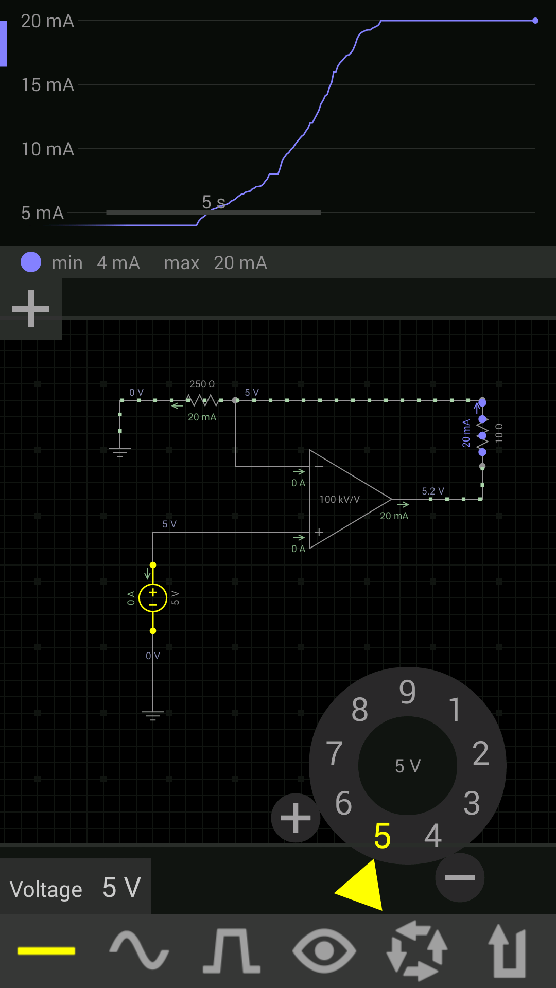
I have done a lot of Googling since and am leaning towards a simple op-amp/transistor setup. Like the diagram below, but using an analogue pin and smoothing cap instead of the zenner to provide the input voltage.
I will prototype it in the coming days and will make up my mind then.
I use same type (4 -20 ma) ultrasonic sensor,simply connect the sensor output series to a 250 ohm resistor and the output to micro-controller directly...why 250 ohm? because
4 ma x 250 ohm =1 v
20 ma x 250 ohm =5v
so u get a 0 to 5 volt analog signal to your controller,but make sure that both the sensor and the controller has common power supply ie powering 24 volt and 5 volt s derived from a single power source,thats what i do and i works for me.hope it helps
I think you misunderstand what I was getting at.
I don't want to to accept a 4-20ma input from a 4-20ms sensor into the arduino.
I want to use the arduino to simulate a 4-20ma sensor. e.g.
Connect a microphone to the arduino and output a 4-20 output according to the volume.
or
Connect a colour sensor to the arduino and output a 4-20 output according to the proportion of red light.
"Voltage To Current Converter Circuit , Lakehead University, Chemical Engineering
The Voltage to Current converter circuit is designed to interface the 0 – 5Volt output of the
Matheson Model 8143 Mass Flow meter to the 4–20mA current loop input of the Bailey Freelance DCS.
The circuit consists primarily of the Burr – Brown XTR110 Voltage to Current converter chip. This chip
can take multiple ranges of voltage input and will give a linear and proportional current output of various
ranges. The configuration of the chip determines the input and output ranges. The following schematic
shows the connections required to have a 0–5V input and give the proportional 4–20mA output current.
The output from the XTR110 are source and gate voltages for a P-channel MOSFET or can be substituted
with the capacitor C2 and the PNP 2N3906 bipolar transistor. The chip allows for callibration via the zero
and span adjust potentiometers R1 and R2.
The remainder of the circuit is a 24Vdc power supply required to drive the XTR110.
This board offers effective, state-of-the-art, reliable linear control of HVAC 4-20mA dampers and valves.
The CONVERTER-VMA420 voltage to current converter is a signal control (Proportional) 4-20 mA voltage to current transducer board for HVAC (Heating, Ventilation and Air Conditioning), electro-hydraulic and servo electronics; actuator, dampers, bleed pilot valve, globe valves, butterfly valves, plug valves, dampers and more.
The CONVERTER-VMA420 board is designed to perform voltage to current conversion (transducer). If used properly, it will eliminate the need for an expensive board, which would otherwise be needed to carry out the same tasks.
The CONVERTER-VMA420 is easy to install, setup, and operate. If you want to do professional remote voltage measurement related functions, The CONVERTER-VMA420 offers the features you need. It can be mounted easily via two 0.125" mounting holes using 4-40 screws.
Simply connect the board to 24VDC or 24VAC connect your voltage source 0-10V to the input and our board will convert it to 0-20mA. For input voltage 2-10V the output current is 4-20mA.
The CONVERTER – VMA420 transducer board is an accurate, linear, and an efficient way to convert industrial standards voltage (input DC voltage models) 0 to 10V, 2 to 10V, 0mV to 1.2V, 66mV to 1.2V, 0mV to 2V, 400mV to 2V,0-5V, 1 to 5V, 0-15V, 3 to 15V, 0-24V, 4.8 to 24V into industrial standards (output current float on 16-20V DC) current 0 to 20mA, 4 to 20mA signals.... See below table "voltage to current industrial standard configuration models".