G'day, I've got a 24V fan that has 4 wires. Here's a link to the datasheet:
http://www.purdyelectronics.com/pdf/PM240-24D-1751B-2TP.pdf
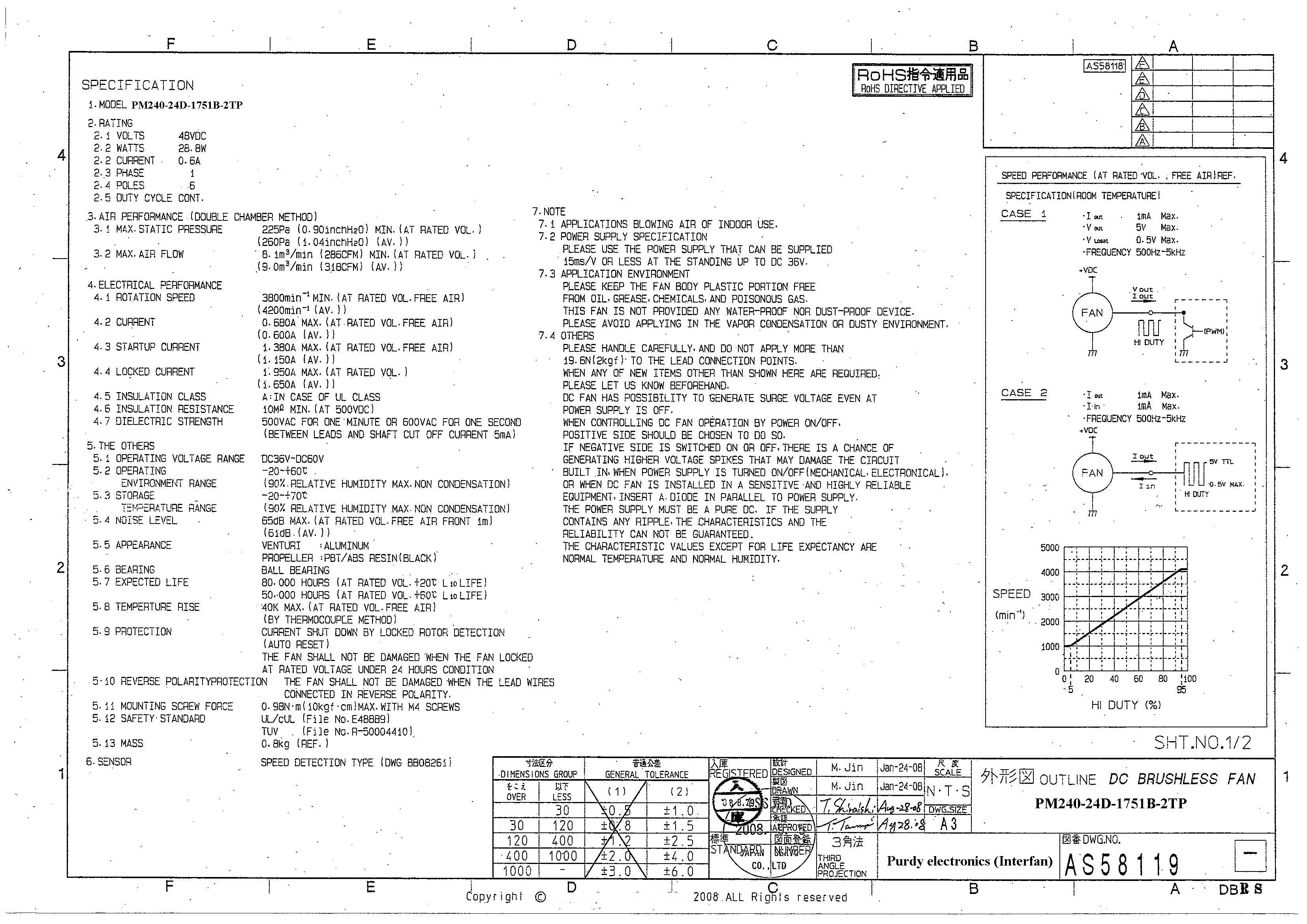
As you may be able to see, one of these wires is marked as CTRL, along with SENSOR, so I thought this may operate in the same way that 4 wire computer fans do, which I have read a few threads about here. I emailed the manufacturer for some more information as that datasheet is lacking, and they sent me 2 documents (attached here), which are a bit confusing because the information seems to conflict with the above datasheet (for a start is says 48V and the blue/yellow wires are switched?)
In the email reply they said "Please review attached page for PWM signal to control speed using pulse width signal input."
I'm a bit of a beginner with electronics and can't really make much sense of the attachments, it seems to indicate speed control is done from 500Hz - 5kHz, this doesn't seem to be in the same range (25kHz) that the 4 wire computer fans do PWM on, so I'm not sure I'm on the right track.
Can anyone make sense of this for me and point me in the right direction on how to do speed control with this fan?
Apply supply positive to red wire, ground to black wire.
The yellow wire can be "read" to get the speed of the rotation. Tie the wire to 5v with 10k (or use internal pull-up R) and count how many times the voltage drops to ground.
The blue wire is used to control the speed using PWM. There are two ways to do so. These are both shown.
Weedpharma
Thanks for the reply.
weedpharma:
The yellow wire can be "read" to get the speed of the rotation. Tie the wire to 5v with 10k (or use internal pull-up R) and count how many times the voltage drops to ground.
This part sounds ok but I can't see where it specifies anything about this - would it be 2x per revolution like other computer fans I've read about?
weedpharma:
The blue wire is used to control the speed using PWM. There are two ways to do so. These are both shown.
I'm not really understanding the difference between the two cases, but from what I've read about other fans I think what I want to do is connect this blue wire directly into pin 5 or 6 (~980Hz PWM) and use analogWrite() between 0-255 for duty cycle. Does this sound right?
Thanks for your help!
The second attachment shows the yellow wire connected to a transistor collector withe the emitter going to ground. This shows that the output is a switch to ground to give the RPM signal. The ratio of pulses I have not looked for.
The PWM signal from the Arduino should be able to to be applied directly to the blue although I have never used PWM.
Weedpharma
Hello Arajag- did you eventually get it to work? I'm also thinking about purchasing this fan
G'day qlittles, sure did, fan has been working great, see here https://github.com/phil-nelson/hukyroaster the roaster.ino has the relevant code