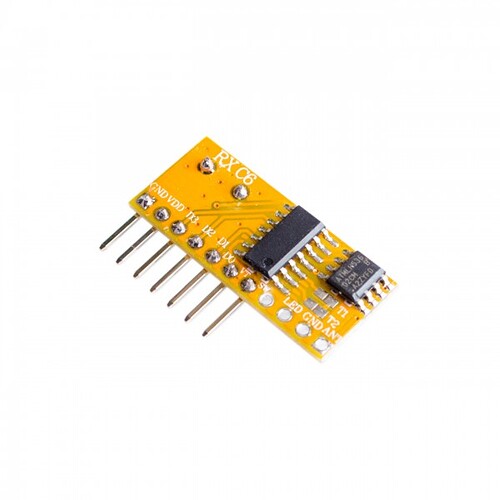
Hi guys, I need a servo to do a sweep toggeled by a 4 channel rf remote. this remote pulls one of its outputs high when a button is pressed on the remote control. this sounded very simple to me but i cant get it to work... Im not very experianced in programming arduino's. I included a picture from the pinout. The remote can be configured to toggle the pin when pressed instead of the momentairy pulse. Please let me know your toughts on how i can tackle this issue.
D3, D2, D1 and D0 corrospond to the buttons on the remote, VT is pulled high when any button is pressed. If T1 is bridged: Interlock function (pin goes high when pressed and only low again when one of the other three buttons is pressed). if T2 is bridged: Toggle function (pin goes high when pressed and low when button is pressed again). T1 and T2 not connected: Reset function (pin only high when button is pressed)
That's interesting. Please post a wiring diagram and your code, in code tags.
What is the mysterious (+) and (-) symbol drawn in black? Okay, wait... I guess you are trying to show a solder jumper on T2. Why would you want to select toggle mode? Is that really compatible with your sketch?
But what about the (+) on the pin?
Did you notice, nothing inside this loop modifies the variable 'active'? So how can it ever exit?
   while (active == 1) {  // d3 high
    servo.write(200);
    delay(300);
    servo.write(-200);
  }
#include <Servo.h>
#define LED_PIN 0
#define BUTTON_PIN 3
Servo myservo;
int pos = 0;
void setup() {
  pinMode(LED_PIN, OUTPUT);
  pinMode(BUTTON_PIN, INPUT);
  myservo.attach(9);
}

void loop() {
  if (digitalRead(BUTTON_PIN) == HIGH) {
    digitalWrite(LED_PIN, HIGH);

  for (pos = 0; pos <= 100; pos += 1) { // goes from 0 degrees to 100 degrees
    // in steps of 1 degree
    myservo.write(pos);              // tell servo to go to position in variable 'pos'
    delay(1);                       // waits for the servo to reach the position
  }
  for (pos = 100; pos >= 0; pos -= 1) { // goes from 100 degrees to 0 degrees
    myservo.write(pos);              // tell servo to go to position in variable 'pos'
    delay(1);                       // waits for the servo to reach the position

  }

  }
  else {
    digitalWrite(LED_PIN, LOW);
  }
}
Looking at the old code again I realise its pretty stupid, the black cross indicates its not connected, the - is just a solderbridge putting the reciever in latch mode. But The new code works, thanks for your feedback
edit: I also added a pulldown resistor from pin 3 to ground
Oops
This topic was automatically closed 180 days after the last reply. New replies are no longer allowed.

