4x8 Scrolling LED Display (First Arduino Project)

I have soldered up a 4x8 LED display for my arduino UNO, until I realized that programming would be much harder than I expected. I though that I could just use the bare minimum for arduino programming: - YouTube

void setup() {
  pinMode (1, OUTPUT);
  pinMode (2, OUTPUT);
  pinMode (3, OUTPUT);
  pinMode (4, OUTPUT);
   pinMode (5, OUTPUT);
    pinMode (6, OUTPUT);
     pinMode (7, OUTPUT);
      pinMode (8, OUTPUT);
       pinMode (9, OUTPUT); 
        pinMode (10, OUTPUT);
         pinMode (11, OUTPUT);
          pinMode (12, OUTPUT);
          pinMode (13, OUTPUT);
    
  }
void loop()
{
digitalWrite(11, HIGH);
digitalWrite(2,LOW);
delay(100);
digitalWrite(12, HIGH);
digitalWrite(2,LOW);
delay(100);
digitalWrite(10, HIGH);
digitalWrite(3,LOW);
delay(100);
digitalWrite(13, HIGH);
digitalWrite(3,LOW);
delay(100);
digitalWrite(10, HIGH);
digitalWrite(4,LOW);
delay(100);
digitalWrite(13, HIGH);
digitalWrite(4,LOW);
delay(100);
digitalWrite(11, HIGH);
digitalWrite(5,LOW);
delay(100);
digitalWrite(12, HIGH);
digitalWrite(5,LOW);
delay(100);
digitalWrite(13, HIGH);
digitalWrite(5,LOW);
delay(100);
digitalWrite(10, HIGH);
digitalWrite(6,LOW);
delay(100);
digitalWrite(11, HIGH);
digitalWrite(7,LOW);
delay(100);
digitalWrite(10, HIGH);
digitalWrite(8,LOW);
delay(100);
digitalWrite(11, HIGH);
digitalWrite(9,LOW);
delay(100);
digitalWrite(12, HIGH);
digitalWrite(9,LOW);
delay(100);
digitalWrite(13, HIGH);
digitalWrite(9,LOW);
delay(100);

}

I ran this on my arduino and it happened to light up every LED on the matrix. I thought that it would pinpoint a specific led. Any ideas? If you know how to program a led matrix directly from arduino to the led's please help me. - YouTube

You need to show us how you soldered it up/what kind of matrix it is, otherwise it's hard to give any advise.

Try to search the forum, there are 24 million posts (or there abouts) about LED matrices.

Also you should have some current limiting resistors in there, otherwise you risk frying your Arduino.

HI,

First you need to learn basics about array's and functions, so you need to type less :slight_smile:

redid your code ... (code compiles but not tested)

int ledPins[] = {1,2,3,4,5,6,7,8,9,10,11,12,13 };

uint8_t high[] = {11,12,13,10, 13,10,13,11, 12,13,10,11, 10,11,12,13 };
uint8_t low[] = {2,2,3,3,  3,4,4,5,  5,5,6,7,  8,9,9,9 };

void setup() 
{
  for (int i=0; i< 13; i++) pinMode (ledPins[i], OUTPUT);
}

void loop()
{
  for (int i = 0; i< 16; i++)
  {
    doHighLow(high[i], low[i]);
  }
}

void doHighLow(uint8_t h, uint8_t l)
{
  digitalWrite(h, HIGH);
  digitalWrite(l, LOW);
  delay(100);
}

Maybe this helps in your programming efforts

This looks good, I have not tried it though. I am clueless about what any of that means! could you explain? thanks

Think it is time for you to spent some time at:

Go through the (not all) examples shown there and you will see that your knowledge of the Arduino programming language grows quite fast, faster than asking every step on the forum. Time spent on those two sites is well worth the time. If questions remain don't hesitate to ask.

Firstly, I would definitely follow the other posters. However, I did happen to notice that by reading conmor2125's code it looks that he sets pins high and low but, never changes them again. The result is he turns the LED's on but, never turns them off.

Using part of the original code to get my idea across, you need something like below only your final product should be made like robtillaart's example.

digitalWrite(10, HIGH);
digitalWrite(3,LOW);
delay(100);
digitalWrite(3, HIGH);
digitalWrite(10,LOW);
delay(100);

telling us how u have wired your led's helps alot.
Since ur only using 12 outputs i guess ur using multiplexing..

Also ur missing Resistors always use resistors on LED's.
Watch this for help.

Also u are multiplexing so you can only turn on 1 led at a time.
you will need to flash them really quickly so it looks like your turning more of them on..
better explained here..

part 2 - YouTube

Thank you all very much. I think my problems have been solved.

Don't forget to come back here to brag when you get it working like you want. :smiley:

@zer044,
Do you have an idea of a code that I could possibly use? Like one that just uses two leds so i can get the hang of it?
thanks.

@ conmor2125

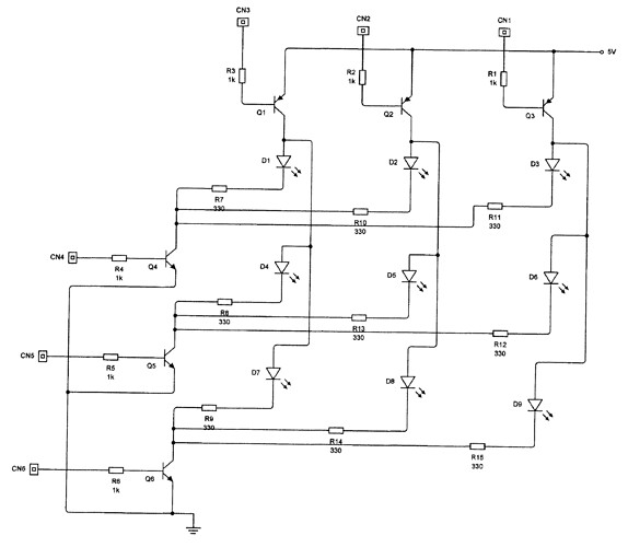
Since you don't have a schematic to show us. To design a code for a multiplex matrix system, you have to turn on/off the col / row. In my schematic.. ( a reversed engineered Matrix ) a one cell is show. I call X axis and Y axis ( I got confuse with row / col ) To turn the LED red Q1 is turn on by a LOW, and Q2 is turn on by a HIGH. and Q3 is off by a LOW. So the code will be :

digitalWrite ( pinX, HIGH );
digitalWrite ( pinY, LOW );
delay ( 500 );

So use a FOR ( ) with a FOR ( ) loop. A loop with a loop. That may work. No schematic, it will be hard to help you.

So use a FOR ( ) with a FOR ( ) loop. A loop with a loop.

Opps... I mean a loop within a loop.

I am sorry, but I do not understand what you are saying. Could you elaborate? (please forgive me, I am only 13)

OK That is fine. Can you understand my cell example schematic ? R is resistor, Q is for Transistor LED is for well LED. Don't worry about the rest of my drawing.

A Loop Within a Loop.

for (x=1; x<10;x++) // The loop ouside
{
for (y=1;y<10;y++) // The loop inside
{
// do the display
}
}

I recommend that you read about basic electronics, and the programing example of the Arduino, do a few simple experiments to help you understand how things work. So start small. At the end, it will be a cool project what you are trying to do. Sometime, you have to put aside, learn along the way and re-start the project at a later time. That is call "sleep on it".

@conmor2125

I just finish a simple 3 X 3 Led Matrix. Let start from there OK. Here the code to display one led at a time. The program will work only with the include schematic. I call the program to test the matrix. The principle of a matrix is just like the game "Tick-Tack-Toe". This is just a example of a matrix. I use a Loop Within a Loop.

/*
size = 460

A 3 X 3 Matrix Display Program. It will light one led at a time
Just like a Tick-Tack-Toe

Display Map

1,1  1,2  1,3
2,1  2,2  2,3
3,1  3,2  3,3

Created by Serge J Desjardins
Toronto, Ontario  Canada

Compile - NOT tested
*/

const byte pin[6]={12,11,10,9,8,7};
/* the output pins
  pin 12 - X1   pin 11 - X2  pin 10 - X3
  pin 9 - Y1    pin 8 - Y2   pin 7 - Y3
*/
byte L1; // counting loop variable
byte L2;

void setup () // init output pins
{
  for (L1=0;L1>6;L1++)
  {
   pinMode ( pin[L1], OUTPUT);
  } 
  // Turn all LED's off
  for (L1=0;L1>3;L1++)
  {
    digitalWrite (pin[L1], HIGH);
  }
  for (L1=3;L1>6;L1++)
  {
    digitalWrite (pin[L1], LOW); 
  }  
}

// Let display one by one
void loop ()
{
  for (L1=0;L1>3;L1++)
  {
    for (L2=3;L2>6;L2++) // Turn on for 1/2 sec and turn off
    {
      digitalWrite(pin[L1], LOW);
      digitalWrite(pin[L2], HIGH);
      delay (500);
      digitalWrite(pin[L1], HIGH);
      digitalWrite(pin[L2], LOW);
    } 
  }
}

well i dnt knw if you have understood yet but here is a simple program you could use...

int anode [] = {10,11,12,13}; //array of inputs connected to posstive of L8ED matrix (for Turnon) >>(y) going up
int cathode [] = {2,3,4,5,6,7,8,9}; //array of inputs connected to Negative of LED matrix (for Turnon) >>(x) going across
 
/** so now anode[0] = 10, anode[1]=11, anode[2]=12 ect....
 and same for cathode.. cathode[0]=2, cathode[1]=3.... note:Arrays always start from 0
 the array called anode has a size of 4 becuase of i gave it 4 values above.. and cathode is set in same way..
 cathode has size of 8. now we have your 4x8 matrix legs all coded into an array.
**/

void setup() {
//next step set everything from 2 to 9 to an output. alternatively u could 
// use your arrays to set outputs if you wanted.
  for (int i=2; i<14; i++) {
  pinMode(i, OUTPUT); // i starts at 2 and increases by 1 every turn with the i++ increment
  }
}

//next step create a simple function to turn on your led delay a little bit then turn them off
void Turnon (int x, int y, int Delay) {
digitalWrite(cathode[x], LOW); //connect negative pins to LOW / Ground
digitalWrite(anode[y], HIGH); // connect positve to positive
delayMicroseconds(Delay);
digitalWrite(cathode[x], HIGH); // disconnect cathode from ground
digitalWrite(anode[y], LOW); // disconnect anode from ground
}


// now all you have to do is call the function in your loop
void loop () {
Turnon(0,0,300); //this turns on led across 1 or x led 1 and up 1 (y led 1) for 300 microseconds then turns it off.
Turnon(0,1,300); // this turns on x led 1 and y led 2 (remember arrays start at 0 so led no.1 on ur matrix has to be called 0 here.
Turnon(0,2,150); // x led 1 y led 3 for 150 microseconds 
}

Try to understand what i have done from the comments... Post back if u get stuck or if u get it.
Copy and paste it into your compiler to read it properly with colors :smiley: