5A relay board

Got the right parts in to assemble an Uno Relay Shield.
Wired up Clock, Data, Latch to SCK, MOSI, SS.
Powered up from 5V. All the relays turn on as intended, indicator lights turn on, looking good.
However, I can't turn them off!

Tried adding 10K pullups across the coil pins (on the bottom of the board) to ensure the open drain outputs were going high - once they go low, they are staying low tho, 0.25V.
What do I need to get a High out to turn the coil off?
parts used:
5V coil relay, G5T-1A
http://www.components.omron.com/components/web/PDFLIB.nsf/0/FE367B32CF6CFE818625739300706BB7/$file/G5T_0609.pdf
coil doide, BAS40H
http://www.nxp.com/documents/data_sheet/BAS40_1PSXXSB4X_SER.pdf
Open Drain shift register TPIC6C595

9V supply into barrel jack. 5V pin measuring 4.8V, regulator getting a little warm.
This has really got me stumped.

My simple program

#include <SPI.h>
byte ssPin = 10;
byte relayArray[] = {
  0x00, 0x01, 0x02, 0x04, 0x08, 0x10, 0x20, 0x40, 0x80,
};
byte x;
void setup(){
  pinMode (ssPin, OUTPUT);
  SPI.begin();
  digitalWrite (ssPin, LOW);
  SPI.transfer(0);                // turn all relays off
  digitalWrite (ssPin, HIGH);
  Serial.begin(9600);
  
}
void loop(){
  for (x=0; x<9; x=x+1){
    digitalWrite (ssPin, LOW);
    SPI.transfer(relayArray[x]); // turn on a relay
    digitalWrite (ssPin, HIGH);
    Serial.print (relayArray[x], HEX); // correct data is being sent
    delay (500);
    digitalWrite (ssPin, LOW);
    SPI.transfer(0);                  // turn all relays off
    digitalWrite (ssPin, HIGH);
    delay(500);
  }
}

DRC checked out?
Solder bridges?
All enables etc. on the 595 are at the proper levels.
Sck looks good all the time?

May have some microscopic copper pathways between pads and traces.

DRC - was good when I ordered the boards.
Solder bridge - can't envision where a solder bridge could be that have the relay start off, turn on, then stay on.
There's certainly none visible.
OE is low, MRCLR is high.
SCK - will have to fire up the scope next I guess.
I plug in 9V, the indicators go on and relays click - watch:

(sorry about the blurryness)

Each one is supposed to turn on, then off - instead it turns on & stays on, nothing turns it off except removing power. Reset the board to rerun the sketch, everything just stays on. Can't figure out where the shift register is getting it's data from.

Edit:
Arduino 595
SS RCK
SCK SRCK

Edited last post

Figured it out after a little nap. Clock & Latch lines to the shift register are mis-labeled. Swapped two wire wrap wires & life is good again :slight_smile:

Went to post - and I see you discovered the same. Thanks :slight_smile:

Did you look at the clock bezels?

Uno relay board in action with 8 LED strings, check it out

What's that playing in the bkgnd (something from CrossRoads, Jr)?

No, I just got an Art of McCartney CD, so it's somebody's cover of Helter Skelter. Lot of big names doing Paul McCartney songs. The ones I heard so far have been pretty true to the music, tho not all played with the same kind of feeling that McCartney, Wings, or the Beatles had. Just really hard to improve on something that was near perfection to start in my opinion. Most covers that attempt to change the music only make it worse, and the ones that sing the main vocals at some lower harmonization because they don't have enough range just make the melody worse too.

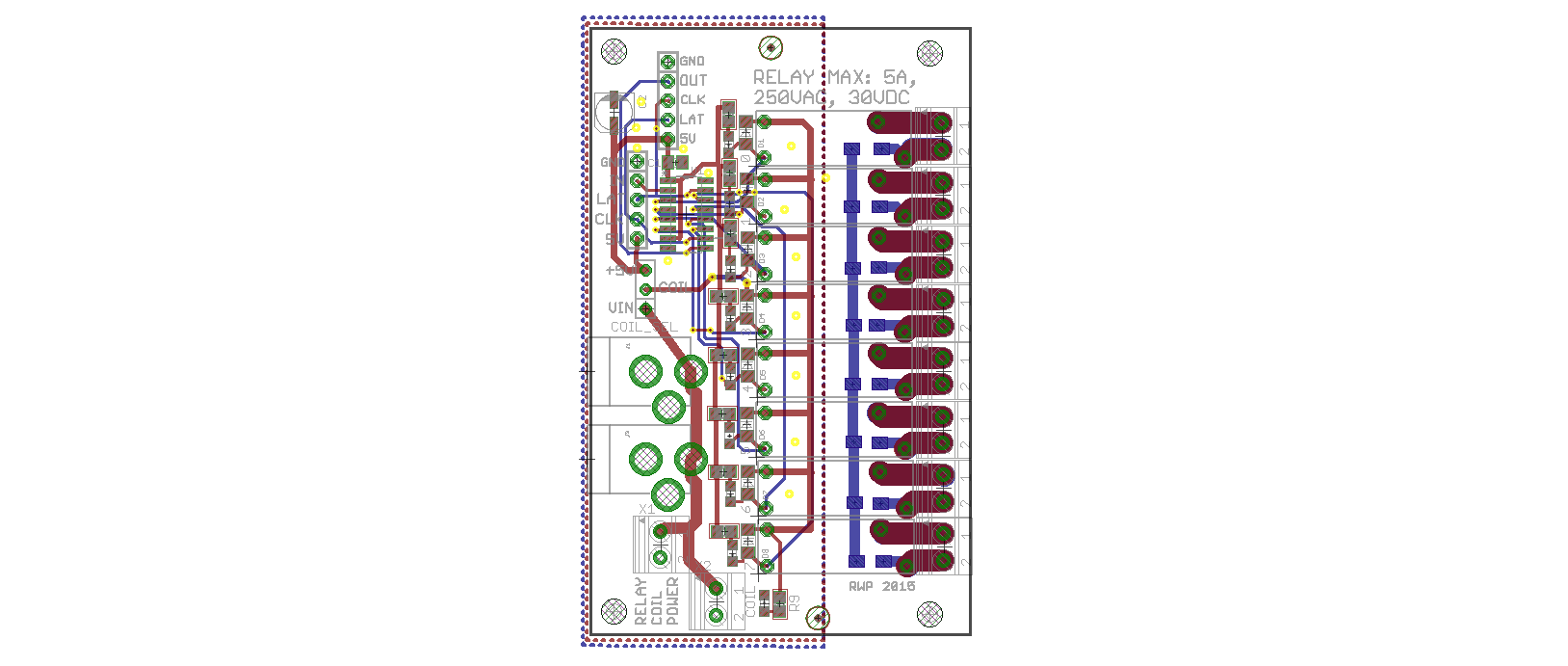
New version of 8-channel "shield" layed out.
Designed with easy daisy chaining in mind, both control and relay power with several options for hardware - barrel jack or 3.5mm screw terminals (or solder wires in the holes).

Couple of tweaks - added 10uF cap to shift register VCC pin to prevent any oddities if the coils are driven from the same 5V line as the shift register.
Added some pads on the back so the contacts could share a common connection, say for a return line in low voltage/low current use. Wouldn't recommend for AC use.