My program has to output a voltage between 0-5V. Before asking this question, I had a misconception on the analogWrite function using PWM. I had done a program based on it. Not getting the result was a disaster as I had spent lots of time refining the program. Is there a way of output-ing a voltage without changing the whole board? I am using Arduino Uno. Any help is appreciated!
Arduino does not have a DAC. You need a DAC.
I am wondering if this works?
SparkFun I2C DAC Breakout - MCP4725
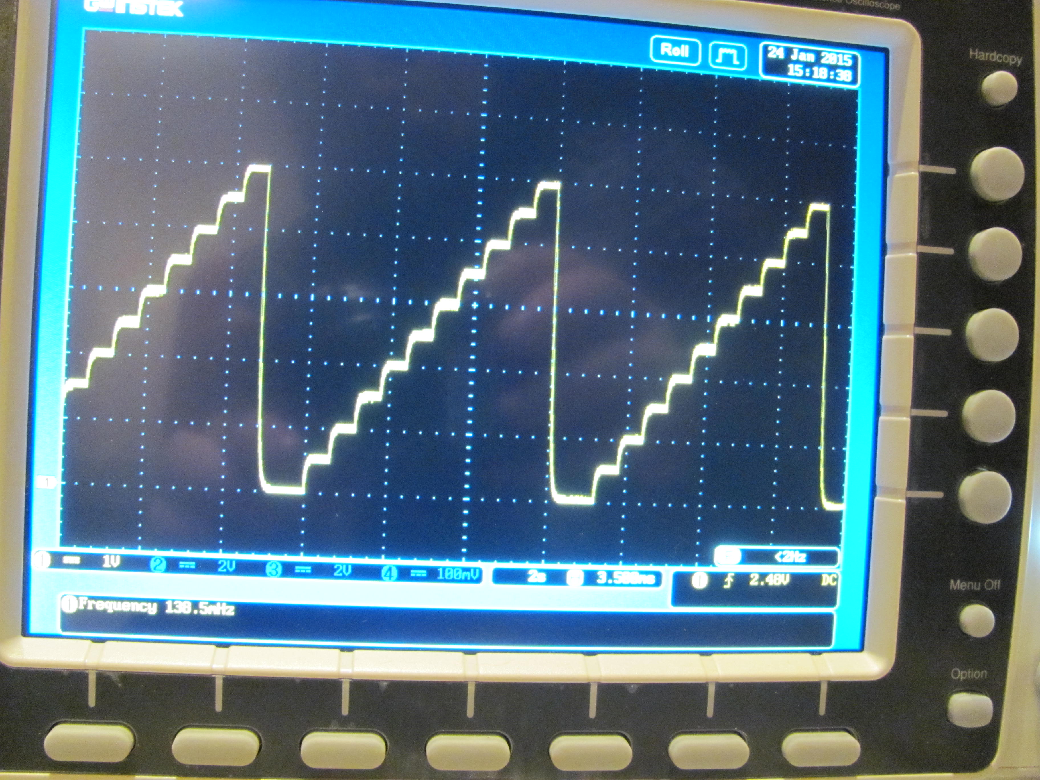
Or use a PWM output with a lowpass filter; here is analogWrite from 0, 25, 50, 75 up to 250.
If 256 steps aren't enough, use a DAC.
I2C, SPI, internal and external reference voltages, multiple outputs, SMD and thruhole parts are available.
http://www.digikey.com/product-search/en/integrated-circuits-ics/data-acquisition-digital-to-analog-converters-dac/2556292?k=dac&k=&pkeyword=dac&pv1989=0&FV=fff40027%2Cfff80184%2Cfffc0096&mnonly=0&newproducts=0&ColumnSort=0&page=1&stock=1&quantity=0&ptm=0&fid=0&pageSize=25
A simple RC lowpass filter can make 0-5volt from a 5volt PWM signal.
But you might need a buffer (opamp) if you are going to load it with something.
Maybe you don't even need a lowpass filter.
Tell us what you are going to do with that voltage, before we give you the wrong advice.
Leo..
Wawa:
A simple RC lowpass filter can make 0-5volt from a 5volt PWM signal.But you might need a buffer (opamp) if you are going to load it with something.
Maybe you don't even need a lowpass filter.
Tell us what you are going to do with that voltage, before we give you the wrong advice.
Leo..
@Wawa - I will be hooking up the voltage to an external programming port of an electronic load. Based on the voltage, it will out put current accordingly.
@CrossRoads - 256 steps meaning 0-255 which the pwm supports right? Based on your picture every step is the increase at "0, 25, 50, 75 up to 250"? If possible I would like a schematic of it too thanks!
Sorry to ask again but,
I am wondering if this works?
SparkFun I2C DAC Breakout - MCP4725
Because this looks simple and easy to implement for me.
Looking at the pictures on sparkfun's tutorial, yes that break-out-board will work.
bryanyon:
"an external programming port of an electronic load"
That tells me nothing about how much drive current that device needs.
That external D/A might or might not work.
Post a link (or diagram) to the device you want to connect.
Leo..
The schematic was nothing fancy - just a 10K resistor and 4.7uF cap to Gnd, the picture is the juncture.

Other values will also work.
http://sim.okawa-denshi.jp/en/CRlowkeisan.htm
@CrossRoads - Thank you. Done according to your schematic and got the results that I wanted!
Cool.