I'm building a laser turret robot with two stepper motors driven by an analog joystick. All is fine as long as the motor uses its own independent power supply but I'd like to power both the motor and the rest (Arduino, joystick) with a single power source.
I've tried connecting a 9V power supply on the UNO's barrel jack then using the Vin and 5V pins to power both motor and logic of the A4988 stepper drivers. The drivers works fine but I get a lot of noise on analog inputs: the signals swing randomly around the correct value as soon as I enable the motor and robot control gets unstable and unreliable.
Is there some solution to get analog inputs working when using a single power supply for both the board and the motors?
The issue you're facing with noise on analog inputs when powering both the Arduino and the motors from a single power supply is likely due to electrical noise generated by the motors
You could place decoupling capacitors across the power and ground pins of the Arduino and the A4988 stepper drivers. you could try to connect a 0.1uF ceramic capacitor between the 5V and GND pins of the Arduino and a larger electrolytic capacitor (e.g., 10uF) across the motor power supply (Vmotor) and ground.
@arod0405
Vin is an input
Don't power your motors through Vin
Please show a schematic how everything is wired ( And look at the advice of @jim-p! )
What type of PSU and what stepper motors are you using? Did you connect the mandatory bulk capacitor near the Vmot of the A4988? 9V is near the minimum what the A4988 needs - higher Voltage is better.
1 Like

I tried adding a 33uF bypass capacitor between Vin and GND on the breadboard with no effect.
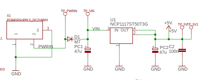
I'm using a simple wall-wart 1,5A PSU with a power jack output. 9V is fine according to the datasheet (8V min). Also, according to UNO R3's page powering via Vin is fine:
External (non-USB) power can come either from an AC-to-DC adapter (wall-wart) or battery. The adapter can be connected by plugging a 2.1mm center-positive plug into the board's power jack. Leads from a battery can be inserted in the GND and Vin pin headers of the POWER connector.
I know using Vin isn't the best practice but what are my options then? My plan is to design a shield with headers for the two drivers and a barrel jack (or screw terminal blocks) to plug an external PS. I've seen designs where a 100uF cap is placed across motor supply pins and I hope that's enough to keep analog inputs running using the same power source for everything. I'll test it on a breadboard soon.
That means, you can power the UNO from the Vin pin ( instead from the barrel jack ). It's a bad idea to power your stepper from the Vin pin, using it as output.
it's meant as an input but it's just a copper track on the PCB.
Skipping the reverse polarity protection diode is not a good idea but there's no other way to get a single power source. As a matter of fact it's the same solution used in the official motor shield.
That would be fine but what you are doing now is just the oppsite.
How am I supposed to test my design until I build a PCB then? All I've got to power the motor with the same source as the board is the Vin pin. Then, again, this is the way the motor shield works:
The product page states:
External (non-USB) power can come either from an AC-to-DC adapter (wall-wart) or battery. The adapter can be connected by plugging a 2.1mm center-positive plug into the Arduino's board power jack on which the motor shield is mounted or by connecting the wires that lead the power supply to the Vin and GND screw terminals, taking care to respect the polarities.
Which is exactly what I'm doing: power jack on the Arduino board to power both the board and the motor+driver.
Just because it was done on an arduino board doesn't mean it's right. I've seen quite a few bad Arduino designs.
They also go on to say:
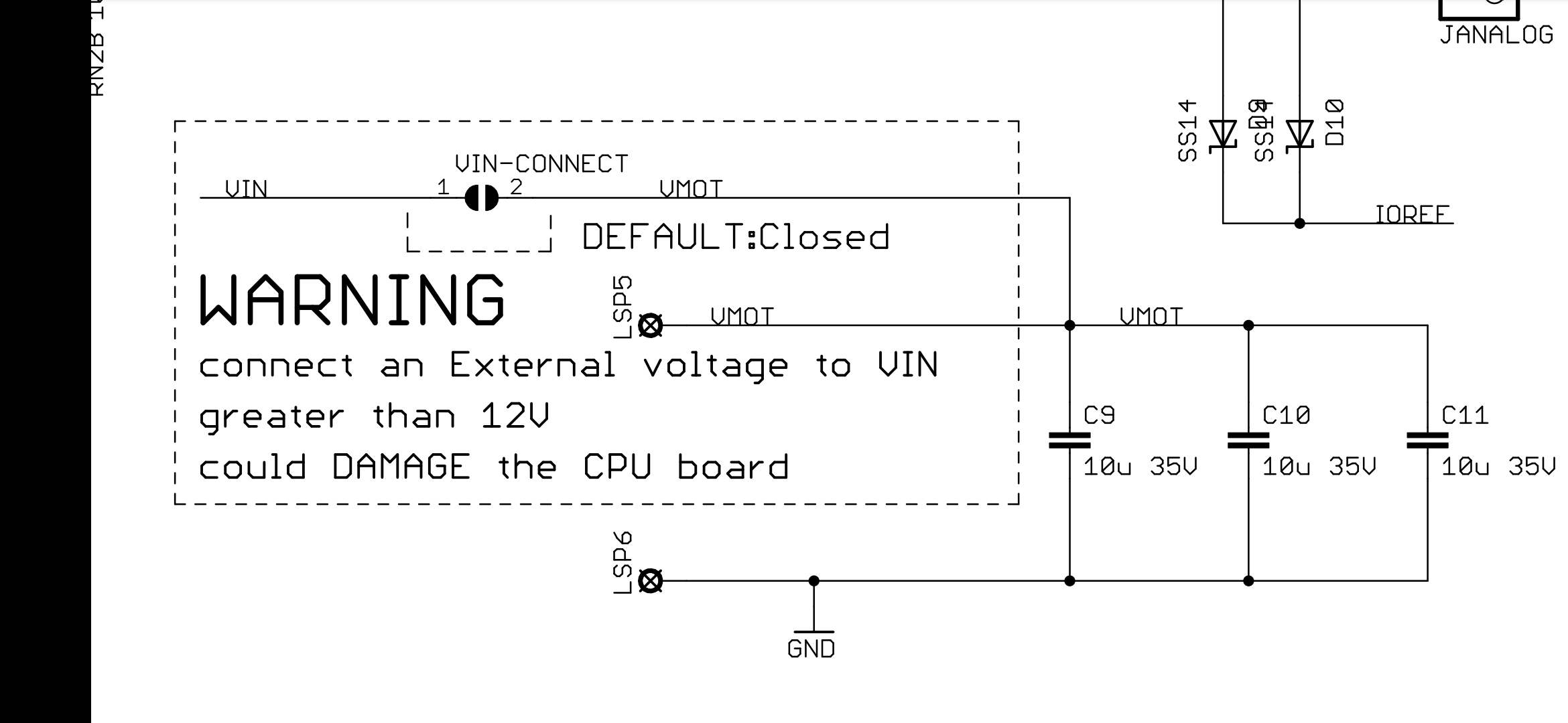
"If your motor require more than 9V we recommend that you separate the power lines of the shield and the Arduino board on which the shield is mounted. This is possible by cutting the "Vin Connect" jumper placed on the back side of the shield."
So you can only use the Arduino barrel jack if you motor need less than 9V but more than 7V.
Does that make sense? Why is there a voltage limit on the motor?
Also, you can't assume that the schematic they post on the product pages are correct. Read the disclaimers.
I hooked up the circuit again this morning and apparently all is fine as long as I use a 12V PSU (1A only) to power:
- Arduino via the barrel jack
- the analog joystick with the 5V Pin
- two A4988 drivers (5V pin and Vin)
It works reliability even with no bypass capacitors. With 9V the same setup fails so maybe it's a PSU related problem. Before that I used different setups with added bypass capacitors (100uF for motor terminals and 100nF for the logic), 12V (to Vin and motor driver pins separately).
For my shield project I'll stick to 12V through the barrel jack plug and add some capacitors. I'll use the Vin pin to power the drivers (or maybe backwards if I find a spare barrel plug to mount on the on the shield).
This topic was automatically closed 180 days after the last reply. New replies are no longer allowed.