I already did. ![]()
Ok, thanks @ec2021 , I see you edited a previous thread and I catch it too late.
I made your connections.
Are your connections random on arduino pins? Or specific for some reason? If they are random, it might mean the connection will be resolved in code. Hmmm, must be it.

Now I have no idea how to make it work in arduino. Heh.
@b707 , do you know what to do from this point on?
As an update, this is the full code that Im having now, with all the modifications so far:
#include "Arduino.h"

void setup() {
Serial.begin(9600);

pinMode(13, INPUT);
pinMode(12, INPUT);
pinMode(11, INPUT);
pinMode(10, INPUT);

}

int pin13State = 0;
int pin12State = 0;
int pin11State = 0;
int pin10State = 0;
int lastpin13State = 0;
int lastpin12State = 0;
int lastpin11State = 0;
int lastpin10State = 0;

bool isNotaccessedAlready=true;

void loop() {

pin13State = digitalRead(13);
pin12State = digitalRead(12);
pin11State = digitalRead(11);
pin10State = digitalRead(10);

isNotaccessedAlready=true;
if (pin13State != lastpin13State || pin12State != lastpin12State || pin11State != lastpin11State || pin10State != lastpin10State)
{
  if(isNotaccessedAlready)
  {
    isNotaccessedAlready=false; // used for possible double readings from the || operators inside this if
    Serial.print(Binaryread3());
    Serial.println();

    lastpin13State=pin13State;
    lastpin12State=pin12State;
    lastpin11State=pin11State;
    lastpin10State=pin10State;
    return;
  }
}

}


int sum = 0;
int Binaryread()
{
  sum=0;
  if (pin13State== HIGH)  sum += 1;
  if (pin12State== HIGH)  sum += 1;
  if (pin11State== HIGH)  sum += 1;
  if (pin10State == HIGH)  sum += 1;
  return(sum);
}
int Binaryread2()
{
byte x = PINB; //PORTB digital pins 8-13
return(x);
}
String Binaryread3()
{
  String out = "";
  out =  (pin13State == HIGH)  ? "1" : "0";
  out += (pin12State == HIGH)  ? "1" : "0";
  out += (pin11State == HIGH)  ? "1" : "0";
  out += (pin10State == HIGH)  ? "1" : "0";
  return out;
}
I am back ...
Thanks for correcting! Coding in a hurry was not a good idea
I came from
int Binaryread4()
{
  int sum;
  sum  = pin13State*8 + pin12State *4 + pin11State *2 + pin10State;
  return(sum);
}
which was okay (and does the same as the left shifts but of course ...) ... ![]()
You can use any digital pin but some can be easily attached to an interrupt for others it requires more effort.
For further info you might look here
https://www.arduino.cc/reference/en/language/functions/external-interrupts/attachinterrupt/
1 Like
Very good you mentioned this detail.

Ok, now I realized, what that INT0 and INT1 means. (interrupt)

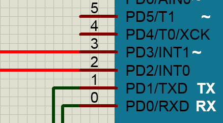
So those lines were to be put on pin2&3 of this arduino board.
I will make the correction in my sim.
Here it is corrected:

I read your interrupt link-page. (Thanks for getting back to my case)
I know this stuff from a lot of reading over the years, in my background. But... im not very familiar with it. I know it exists, but not into it. Kind of rookie at it.
But I get the idea.
Now, let's see in practice. Haha.

I got this from the TI datasheet

If I am not wrong the ADC cycle starts with a short LOW/HIGH/LOW on the START line.
End of conversion is signalised by a change of EOC from LOW to HIGH.
I tried to simulate the ADC behaviour in principle not in exact timing:
#include "Arduino.h"

constexpr int startPin      = 4;  // pin from UNO to ADC START
constexpr int eocPin        = 2;  // pin from ADC EOC to UNO

// The next pins used to simluate the ADC
constexpr int adcEOCpin     = 5;  // pin from UNO that simulates ADC EOC output pin
constexpr int adcStartPin   = 3;  // pin from UNO that simulates ADC START input pin


void setup() {
  Serial.begin(9600);

  // Changed from INPUT to INPUT_PULLUP for Wokwi
  // The slide switches have been "modified" in diagram.json not to bounce!
  pinMode(13, INPUT_PULLUP);
  pinMode(12, INPUT_PULLUP);
  pinMode(11, INPUT_PULLUP);
  pinMode(10, INPUT_PULLUP);

  pinMode(startPin, OUTPUT);
  pinMode(eocPin, INPUT);

  // Interrupt routine that just reports that data are available
  attachInterrupt(digitalPinToInterrupt(eocPin), setDataAvailable, HIGH);

  // Simulating ADC
  // --------------------------------------------------------------------------
  pinMode(adcEOCpin, OUTPUT);
  pinMode(adcStartPin, INPUT);
  digitalWrite(adcEOCpin, HIGH);  // EOC seems to be HIGH if conversion not active
  attachInterrupt(digitalPinToInterrupt(adcStartPin), setStart, RISING);
  // --------------------------------------------------------------------------
}

boolean convertingOn = false;
boolean dataAvailable = false;

// Only for ADC simulation
boolean startConverting = false;

void loop() {
  startADCCycle();
  simADC();  // Simulates the ADC "conversion" time
  handleData();
}

void startADCCycle() {
  if (!convertingOn) {
    digitalWrite(startPin, HIGH);  // set START Pin to High
    delayMicroseconds(100);
    digitalWrite(startPin, LOW);  // set START Pin to LOW again
    delayMicroseconds(100);
    digitalWrite(startPin, HIGH);  // set START Pin to High
    convertingOn = true;
  }
}

void handleData() {
  if (dataAvailable) {
    convertingOn = false;
    dataAvailable = false;
    printData();
  }
}

void setDataAvailable() {
  dataAvailable = true;
}


void printData() {
  int pin13State = 0;
  int pin12State = 0;
  int pin11State = 0;
  int pin10State = 0;
  static int lastpin13State = 1;
  static int lastpin12State = 1;
  static int lastpin11State = 1;
  static int lastpin10State = 1;

  pin13State = digitalRead(13);
  pin12State = digitalRead(12);
  pin11State = digitalRead(11);
  pin10State = digitalRead(10);
  if (pin13State != lastpin13State || pin12State != lastpin12State || pin11State != lastpin11State || pin10State != lastpin10State)
  {
    String out = "";
    out =  (pin13State == HIGH)  ? "1" : "0";
    out += (pin12State == HIGH)  ? "1" : "0";
    out += (pin11State == HIGH)  ? "1" : "0";
    out += (pin10State == HIGH)  ? "1" : "0";
    Serial.println(out);
    lastpin13State = pin13State;
    lastpin12State = pin12State;
    lastpin11State = pin11State;
    lastpin10State = pin10State;
  }
}

// Simulates the ADC functions START and EOC

void setStart() {
  startConverting = true;
}

void simADC() {
  static boolean isConverting = false;
  static unsigned long startTime = 0;
  if (isConverting) {
    if (millis() - startTime > 500) {   // ADC conversion time takes 500 msec ... very long but just for
                                        // the principle
      digitalWrite(adcEOCpin, LOW);
      delayMicroseconds(100);
      digitalWrite(adcEOCpin, HIGH);
    }
  } else {
    isConverting = startConverting;
    if (isConverting) {
       startConverting = false;
       startTime = millis();
    }
  }
}
See also here https://wokwi.com/projects/364457860178684929
There may be still some space for improvement but it might show the principle.

I used the pins 5 and 3 to simulate/emulate the functionality of the START and EOC pin of the ADC.
Hope there are no big mistakes in it. Still some work for you left ... ![]()
1 Like
I dont understand your code.
I have 1 output and 1 input from Arduino to the ADC
const byte ledPin = 4; //for tests only
const byte interruptEOC = 3;//output for ADC0808, but input from Arduino
const byte interruptSTART = 2;//input for ADC0808, but output from Arduino
While in your sample code, you have 2 output and 2 input from Arduino to the (simulated) ADC. It is too confusing for me. Can you simplify your code to
1- fit my pin numbers (2&3)
2- fit my number of pins I'm using, 1 output and 1 input from Arduino to the ADC
Thanks.
I really tried your code and Im lost too soon to even start anything. I will try it some more if you cant help, but... its a bit too much.
Good morning and thank you for yesterday help !
I managed to clean and adapt your code to my pins I have here, but... nothing works.
I removed "pins used to simluate the ADC" and everything related to them.
Then I removed the bool "convertingOn" because I noticed the START was being hold High all the time with that variable in code. After removing it, the START start blinking. But still no terminal output. The EOC is hold LOW all the time.
I notice EOC is only used in void setup() but not at all in the void loop() as START is. Thats why START is blinking.
I noticed you followed the "attachinterrupt" code example order of things. There I got myself stuck since in our case we have a IN and a OUT to care about, while in the example is only an OUT deal with. So you managed the impossible for me so far.
Hard job, eh?
Here is the 'adapted' code:
#include "Arduino.h"

constexpr int eocPin        = 3;  // pin from ADC EOC to UNO//output for ADC0808, but input from Arduino
constexpr int startPin      = 2;  // pin from UNO to ADC START//input for ADC0808, but output from Arduino

void setup() {
  Serial.begin(9600);

  // Changed from INPUT to INPUT_PULLUP for Wokwi
  // The slide switches have been "modified" in diagram.json not to bounce!
  pinMode(13, INPUT_PULLUP);
  pinMode(12, INPUT_PULLUP);
  pinMode(11, INPUT_PULLUP);
  pinMode(10, INPUT_PULLUP);

  pinMode(startPin, OUTPUT);
  pinMode(eocPin, INPUT);

  // Interrupt routine that just reports that data are available
  attachInterrupt(digitalPinToInterrupt(eocPin), setDataAvailable, HIGH);
}


boolean dataAvailable = false;

// Only for ADC simulation
boolean startConverting = false;

void loop() {
  startADCCycle();
  handleData();
}

void startADCCycle() {
    digitalWrite(startPin, HIGH);  // set START Pin to High
    delayMicroseconds(100);
    digitalWrite(startPin, LOW);  // set START Pin to LOW again
    delayMicroseconds(100);
    digitalWrite(startPin, HIGH);  // set START Pin to High
}

void handleData() {
  if (dataAvailable) {
    dataAvailable = false;
    printData();
  }
}

void setDataAvailable() {
  dataAvailable = true;
}


void printData() {
  int pin13State = 0;
  int pin12State = 0;
  int pin11State = 0;
  int pin10State = 0;
  static int lastpin13State = 1;
  static int lastpin12State = 1;
  static int lastpin11State = 1;
  static int lastpin10State = 1;

  pin13State = digitalRead(13);
  pin12State = digitalRead(12);
  pin11State = digitalRead(11);
  pin10State = digitalRead(10);
  if (pin13State != lastpin13State || pin12State != lastpin12State || pin11State != lastpin11State || pin10State != lastpin10State)
  {
    String out = "";
    out =  (pin13State == HIGH)  ? "1" : "0";
    out += (pin12State == HIGH)  ? "1" : "0";
    out += (pin11State == HIGH)  ? "1" : "0";
    out += (pin10State == HIGH)  ? "1" : "0";
    Serial.println(out);
    lastpin13State = pin13State;
    lastpin12State = pin12State;
    lastpin11State = pin11State;
    lastpin10State = pin10State;
  }
}
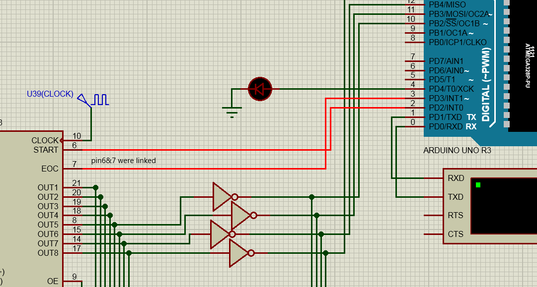
For clarity, here is how the wiring looks in my sim:

Ec2021: This user's public profile is hidden. I can not add you to my friend list. You add me ! ;) Thanks.
I am not sure if I have time today and the next days ... we'll see.
However, I changed my sketch to come closer to the "real" thing by limiting the call of the conversion to a given time
void startADCCycle(unsigned long everyXmsec)
make the simADC() much quicker and let it set the adcEOCpin to LOW only during this time.
The eocPin interrupt is called when eocPin receives a RISING signal.
The adcStartPin interrupt is called when it receives a FALLING signal.
That replicates the timing better than the sketch before (I hope).
Sketch:
#include "Arduino.h"

constexpr int startPin      = 4;  // pin from UNO to ADC START
constexpr int eocPin        = 2;  // pin from ADC EOC to UNO

// The next pins used to simluate the ADC
constexpr int adcEOCpin     = 5;  // pin from UNO that simulates ADC EOC output pin
constexpr int adcStartPin   = 3;  // pin from UNO that simulates ADC START input pin


void setup() {
  Serial.begin(9600);

  // Changed from INPUT to INPUT_PULLUP for Wokwi
  // The slide switches have been "modified" in diagram.json not to bounce!
  pinMode(13, INPUT_PULLUP);
  pinMode(12, INPUT_PULLUP);
  pinMode(11, INPUT_PULLUP);
  pinMode(10, INPUT_PULLUP);

  pinMode(startPin, OUTPUT);
  pinMode(eocPin, INPUT);

  // Interrupt routine that just reports that data are available
  attachInterrupt(digitalPinToInterrupt(eocPin), setDataAvailable, RISING);

  // Simulating ADC
  // --------------------------------------------------------------------------
  pinMode(adcEOCpin, OUTPUT);
  pinMode(adcStartPin, INPUT);
  digitalWrite(adcEOCpin, HIGH);  // EOC seems to be HIGH if conversion not active
  attachInterrupt(digitalPinToInterrupt(adcStartPin), setStart, FALLING);
  // --------------------------------------------------------------------------
}

boolean convertingOn = false;
boolean dataAvailable = false;

// Only for ADC simulation
boolean startConverting = false;

void loop() {
  startADCCycle(10);
  simADC();  // Simulates the ADC "conversion" time
  handleData();
}

void startADCCycle(unsigned long everyXmsec) {
  static unsigned long lastCycle = 0;
  if (!convertingOn && millis()-lastCycle >= everyXmsec) {
    digitalWrite(startPin, HIGH);  // set START Pin to High
    delayMicroseconds(100);
    digitalWrite(startPin, LOW);  // set START Pin to LOW again
    convertingOn = true;
    lastCycle = millis();
  }
}

void handleData() {
  if (dataAvailable) {
    convertingOn = false;
    dataAvailable = false;
    printData();
  }
}

void setDataAvailable() {
  dataAvailable = true;
}

void printData() {
  int pin13State = 0;
  int pin12State = 0;
  int pin11State = 0;
  int pin10State = 0;
  static int lastpin13State = 1;
  static int lastpin12State = 1;
  static int lastpin11State = 1;
  static int lastpin10State = 1;

  pin13State = digitalRead(13);
  pin12State = digitalRead(12);
  pin11State = digitalRead(11);
  pin10State = digitalRead(10);
  if (pin13State != lastpin13State || pin12State != lastpin12State || pin11State != lastpin11State || pin10State != lastpin10State)
  {
    String out = "";
    out =  (pin13State == HIGH)  ? "1" : "0";
    out += (pin12State == HIGH)  ? "1" : "0";
    out += (pin11State == HIGH)  ? "1" : "0";
    out += (pin10State == HIGH)  ? "1" : "0";
    Serial.println(out);
    lastpin13State = pin13State;
    lastpin12State = pin12State;
    lastpin11State = pin11State;
    lastpin10State = pin10State;
  }
}

// Simulates the ADC functions START and EOC
void setStart() {
  startConverting = true;
}

void simADC() {
  static boolean isConverting = false;
  static unsigned long startTime = 0;
  if (isConverting) {
    if (micros() - startTime > 500) {   // Only assumption: ADC conversion time takes 500 microseconds
      digitalWrite(adcEOCpin, HIGH);
      isConverting = false;
    }
  } else {
    isConverting = startConverting;
    if (isConverting) {
       startConverting = false;
       startTime = micros();
       digitalWrite(adcEOCpin, LOW);
    }
  }
}
Simulation: https://wokwi.com/projects/364499421812168705
Schematic as before.
If I have got some time I will have a look but I cannot promise ...
Good luck!
In minimum you might try to set
attachInterrupt(digitalPinToInterrupt(eocPin), setDataAvailable, RISING);
I made a "quick and dirty trick": I copied your code to Wokwi, modified just this line above and linked pin 2 and 3 ...

Now the startADCCycle() creates the EOC signal itself (Rising edge from HIGH to LOW) and ... it works in the simulation. See https://wokwi.com/projects/364501658760531969
I guess that from here on you must find the way in Proteus, e.g. by checking the line status on your scope. You could check the ADC0808 datasheet also for information about the required timing of START to start the ADC conversion (there is a tws in the drawing ?!?)
mister ec2021 - thank you for your support so far.
This is definitely a high level problem we are dealing here.
I manage to make something work... and I managed to understand some 'logic'. But like you, Im not completely sure is correct. I might get VERY lucky and I cant be sure how it will work in reality, compared to this simulation Im doing. The good news is that is working for now. And for what I can say so far, no double output on the terminal...but I didnt do an extensive test on it.
This time I got some skipped readings....

Ive added that diode (and that wire link as it was originally). Im not completly sure how good it is... but for some reason it is...kind of working like this.

The most important fragment of code I concentrated was this:

Here is my full modified code:
#include "Arduino.h"

constexpr int eocPin        = 3;  // pin from ADC EOC to UNO//output for ADC0808, but input from Arduino
constexpr int startPin      = 2;  // pin from UNO to ADC START//input for ADC0808, but output from Arduino

void setup() {
  Serial.begin(9600);

  // Changed from INPUT to INPUT_PULLUP for Wokwi
  // The slide switches have been "modified" in diagram.json not to bounce!
  pinMode(13, INPUT_PULLUP);
  pinMode(12, INPUT_PULLUP);
  pinMode(11, INPUT_PULLUP);
  pinMode(10, INPUT_PULLUP);

  pinMode(startPin, OUTPUT);
  pinMode(eocPin, INPUT);

  // Interrupt routine that just reports that data are available
  attachInterrupt(digitalPinToInterrupt(eocPin), setDataAvailable, CHANGE);
}

boolean dataAvailable = false;

void loop() {
  startADCCycle();
}

void startADCCycle() {
    digitalWrite(startPin, HIGH);  // set START Pin to High
    digitalWrite(startPin, LOW);  // set START Pin to LOW again
    handleData();
}

void handleData() {
  if (dataAvailable) {
    dataAvailable = false;
    printData();
  }
}

void setDataAvailable() {
  dataAvailable = true;
}

void printData() {
  int pin13State = 0;
  int pin12State = 0;
  int pin11State = 0;
  int pin10State = 0;
  static int lastpin13State = 1;
  static int lastpin12State = 1;
  static int lastpin11State = 1;
  static int lastpin10State = 1;

  pin13State = digitalRead(13);
  pin12State = digitalRead(12);
  pin11State = digitalRead(11);
  pin10State = digitalRead(10);
  if (pin13State != lastpin13State || pin12State != lastpin12State || pin11State != lastpin11State || pin10State != lastpin10State)
  {
    String out = "";
    out =  (pin13State == HIGH)  ? "1" : "0";
    out += (pin12State == HIGH)  ? "1" : "0";
    out += (pin11State == HIGH)  ? "1" : "0";
    out += (pin10State == HIGH)  ? "1" : "0";
    Serial.println(out);
    lastpin13State = pin13State;
    lastpin12State = pin12State;
    lastpin11State = pin11State;
    lastpin10State = pin10State;
  }
}
If I am not wrong you are now handling the START line without checking whether a previous conversion is already over. Maybe that it is ignored by the ADC0808...
It would be more straightforward to trigger the conversion, poll for dataAvailable and start the next conversion after reading the data.
That could be done by a separate boolean conversionStarted which you set to false in setup, to true when you handled the START line and to false again after reading the data.
Pseudocode:
if (!conversionStarted) {start conversion}
(because I wrote this on my Smartphone... ![]() l
l
Some updates:
I changed the clock fv to different values, but absolutely no difference in any case so I defaulted it to my original test fv of 10kHz. I change it to 640kHz as it is typical in the datasheet and the maximum as well 1280kHz (1.2MHz). Nothing, no difference. The errors are exactly the same as with 10kHz. So I leave it at that, since Proteus simulator is notorious for crapping itself at high speeds (in some cases).

I reversed to my very beginning code, the one I started with here in the forum, and the ADC pin 6&7 are linked together, and not to the arduino anymore. I got more errors and problems with those pins linked to arduino than when they were linked together.

Also I find this little detail in datasheet of the ADC0808:

Ive turned the code around, in the hope I can obtain some insight into the ADC functionality... and this new code is giving me the same results(and errors) as before; but is interesting this way, because is different approach. So the code itself is not doing the error. The chip is.
String group1="";

void loop() {
pin13State = digitalRead(13);
pin12State = digitalRead(12);
pin11State = digitalRead(11);
pin10State = digitalRead(10);


  //if any pins are changing
  if (pin13State != lastpin13State || pin12State != lastpin12State || pin11State != lastpin11State || pin10State != lastpin10State)
  {
    delay(10);
    group1 += BinaryRead()+"\r";
    //group1 += Serial.println();
    lastpin13State=pin13State;
    lastpin12State=pin12State;
    lastpin11State=pin11State;
    lastpin10State=pin10State;

    if (BinaryRead()== "1111")
    {
    group1 += BinaryRead()+"\r\r"; // show 1111 result as well in group1
    Serial.print(group1);
    group1=""; //reset
    }
  }
}
What this does, is spitting a single string that is looking like a single block there:
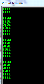
Those groups are a single string, not 4 as before. The last 1111 are 2 times in the circuit logic, and that part is not a 'double' error, that is ok. But between the 1111's there are the important errors that are happening.
Ive included a delay(10); in the hope it will delay any spurious readings... I change it to many values but nothing. So it appears there are no transients on the input pins of the arduino. I thought it might be the case. Even if I looked into it with the osciloscope. Double checking never hurts, right? Thanks for reading.
End of update.
I made it work !!!!
And I finally understood what the hell is going on !!! WOW.... it was crazy hard !
Unbelievable. Ohohoaaa....
So my target was to make this ADC0808 commanded from arduino board, or any other MCU / logic ccts / PIC / procesor. Ok? Now I figure it out. It is deviously simple. I cant say I understood it in DEPTH but for the results I get so far, YAH, is working "by the book". Ohohoaaa....
Haha, NOW !!! Im happy !
So, many thanks to mister @ec2021. You steer me in the right direction when you pointed to "working synchronously". The code I made and also the cct, is not using the interrupt method you actually pointed to. It is using normal in-out pins. I will have to give it a try with the interrupt function example as you originally intended. But now I know what pin goes where ! that was the biggest issue I faced and now - uhuu - I gracefully (and very hard) resolved it.
Oh Yah !
Oh Yah !
Here is the cct setup:

Here is the code:
//test - backup9 working synchronously
#include "Arduino.h"

void setup()
{
Serial.begin(9600);

pinMode(13, INPUT);
pinMode(12, INPUT);
pinMode(11, INPUT);
pinMode(10, INPUT);

pinMode(2, INPUT);//EOC output from ADC0808, but input for Arduino
}


String group1="";
bool isReadOnce = true;
void loop()
{
  if(digitalRead(2) == HIGH)
  {
    if(isReadOnce)
    {
      isReadOnce = false;
      group1 += BinaryRead()+"\r";

      if (BinaryRead()== "1111")
      {
        group1=""; //reset
        group1 += BinaryRead()+"\r\r";
      }
      Serial.print(group1);
      group1="";  //reset
    }
  }
  else
  {
    isReadOnce = true;
  }

}


String BinaryRead()
{
  String out = "";
  out =  (digitalRead(13) == HIGH)  ? "1" : "0";
  out += (digitalRead(12) == HIGH)  ? "1" : "0";
  out += (digitalRead(11) == HIGH)  ? "1" : "0";
  out += (digitalRead(10) == HIGH)  ? "1" : "0";
  return out;
}
And here is the output on the Terminal:

Errors:
In the very begining, when is starting, is adding a double or weird number (sometimes), especially when is set to autorun in fast mode.
When you stop the automatic (fast) clock, is adding (sometimes) random or double readings.
But while in the process, everything runs OK.
So the start and the end are a bit of a problem. Probably is a simulator problem.
-----f-----
But if clocked Manually, everything is working Excellent !
Today I will attempt to adapt the code that is working already to the interrupt mode that I tried desperately and failed so far. Wish me luck.
Success!___I did it and is working !
Thank you @ec2021 for your assistance ! Excellent.
I also added some insightful comment about how I understand it.
You're welcome.
-full code with an interrupt-
//test - backup10 functional interrupt
//https://www.arduino.cc/reference/en/language/functions/external-interrupts/attachinterrupt/
//http://gammon.com.au/interrupts
#include "Arduino.h"

void setup()
{
Serial.begin(9600);

pinMode(13, INPUT);
pinMode(12, INPUT);
pinMode(11, INPUT);
pinMode(10, INPUT);

pinMode(2, INPUT_PULLUP);//EOC output from ADC0808, but input for Arduino and special interrupt pin as INT0 on the board
attachInterrupt(digitalPinToInterrupt(2), _INT0, CHANGE);//attach interrupt handler
}


void loop()
{

// this is the main loop function in arduino and is not used for 'interrupt'

}


String group1="";
bool isReadOnce = true;
void _INT0() //used for interrupt function
{
  /* This is a normal function passed as an argument into an interrupt handler
   * Only void type is allowed
   * It is exactly as you would use a secondary loop function (loop2)
   * (in arduino only 1 loop function is allowed)
   * The interrupt handler listen to pin2 and execute this function when that pin changes
   * Other parameters are for 1 time use, so use CHANGE parameter for continuous feedback
   */
  if(digitalRead(2) == HIGH)
  {
    if(isReadOnce)
    {
      isReadOnce = false;
      group1 += BinaryRead()+"\r";

      if (BinaryRead()== "1111")
      {
        group1=""; //reset
        group1 += BinaryRead()+"\r\r";
      }
      Serial.print(group1);
      group1="";  //reset
    }
  }
  else
  {
    isReadOnce = true;
  }
}
String BinaryRead()
{
  String out = "";
  out =  (digitalRead(13) == HIGH)  ? "1" : "0";
  out += (digitalRead(12) == HIGH)  ? "1" : "0";
  out += (digitalRead(11) == HIGH)  ? "1" : "0";
  out += (digitalRead(10) == HIGH)  ? "1" : "0";
  return out;
}
Also is important to add, that the simulation in Proteus is better with this code ! Tiny but important improvement. Very nice.
Great that you solved the issue on your own. That's mostly the best solution because it helps for further challenges!
I do not doubt that your solution with the interrupt function works as you expect. However there are some things you should consider when using interrupts in future:
- It is not recommended to use Serial.print() functions in an interrupt: Reason is that interrupts do not only "interrupt" the usual loop() business but also stops further functions which are of vital interest for the overall functionality. Therefore interrupt functions should consume only a minimum of time. Usually only time critical parts are done in an interrupt, like retrieving data from an external port and/or setting some "flags" that tell the application that runs in loop() that something has happened. Serial is definitely not one of the tasks to be called in an ISR (interrupt service routine).
- If variables are changed in an ISR it may be done while the loop() application also tries to read or modify it. This may lead to unexpected behaviour, especially when the data type is longer than one byte. You may read here https://reference.arduino.cc/reference/en/language/functions/interrupts/nointerrupts/ and also here https://roboticsbackend.com/arduino-interrupts/. The keyword "volatile" is often suggested together with interrupts but it is more relevant for the use with hardware registers (ports) that change their data driven by external functions. nointerrupts() / interrupts() should be sufficient in loop() applications (outside of an ISR!) to ensure proper reading/setting of variables shared between loop() and an ISR.
1 Like