I am using a four digit seven segment display led panel common cathode connected to an Arduino UNO.
In some tutorials related to this which I saw on the internet, they are connecting the GPIO pins , however in between there is the led panel and a resistor. Also one GPIO pin is HIGH whiel the other is LOW and they are connected together as I mentioned above. Would't there be a short circuit and the board will burn out.
Also, what are the pins of the four digit seven segment which should have resistors connected to?
Also,I have the same problem with a 8 by 8 dot matrix?
It is not wise to connect two OUTPUT pins together without a current-limiting resistor between them. There is indeed a great risk of damage to the pins due to a short circuit.
Connecting two INPUT pins or and INPUT and an OUTPUT will not cause a problem.
groundFungus:
What 7 segment display? How are we to know which 7 segment display that you have?
The standard 7 segment display. Are there more than one types?.My one is common cathode.
Robin2:
It is not wise to connect two OUTPUT pins together without a current-limiting resistor between them. There is indeed a great risk of damage to the pins due to a short circuit.
Connecting two INPUT pins or and INPUT and an OUTPUT will not cause a problem.
...R
I am connecting two OUTPUT pins but in between there is a resistor 220 ohms and led panel. One pin is high and the other low. Isn't that exactly what we are told to avoid?
SparkingBoards:
I am connecting two OUTPUT pins but in between there is a resistor 220 ohms and led panel. One pin is high and the other low. Isn't that exactly what we are told to avoid?
That sounds perfectly reasonable. One I/O pin acts as power and the other as GND. The 220 ohm resistor and the voltage drop across the diode limit the current to a level that the I/O pins are comfortable with.
However for a seven segment display or a matrix, since you will be powering more than one segment when you pull a digit cathode LOW, the resistors in the segment anodes need to be 1k to limit the common cathode current.
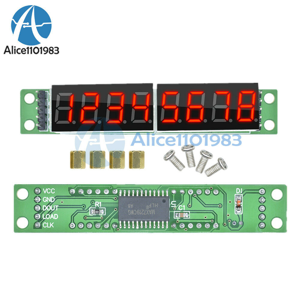
This is only for "educational" playing around with a seven segment or matrix display. For any genuine projects, you use a module with a proper MAX7219 display driver.
eBay!
But it would be preferable to wait until normal business resumes and the prices return to the more realistic pre-COVID-19 situation - if that actually happens.