The available power at the secondary side of the isolated xformer makes it possible to carry out realistic measurements.
Working at the 220V live side with huge grid power is really lethal than working with isolated 220V with limited 500 W (max) power. In the Electrical Lab, it is a common practice to use 500 VA isolated xformer and Variac to do experiments on 3-phase and single supplies (of course with prescribed saftey precautions).
You are right. You pay more to get worse precision and some dubious safety?
Of course you often don't want (or dare) to break the wire to add the measuring resistor. But when you mess with the mains voltage for some other reason I see no benefit in the current transformer.
The other aspect not touched on here is adding a series resistance changes the circuits prospective fault current and may make the fuse disconnect time longer -possibly too long .
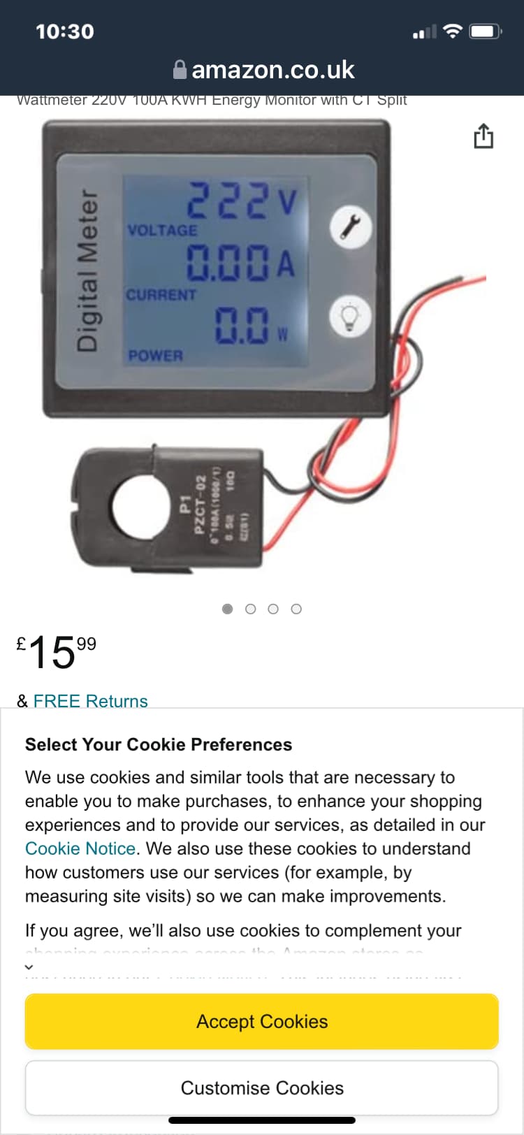
The truth is it’s a pointless dangerous method and a CT is a better solution that can give you a higher voltage output than the resistor and is cheap, and doesn’t involve breaking into the circuit .
We don’t know the OP’s ability and shouldn’t recommend it
Can the CT measure DC current (such in case the load users half wave rectifying)? What is its high frequency response? Can it measure i.e. switching power supply reliably?
Now you are adding complications not originally there in your post .
You seem set in your way to use a shunt whatever anyone says , so I’m not sure what you want in a reply
A CT can measure such signals to an extent as they represent harmonics on top of the fundamental. You need to look at specs . Will your software be able to handle such signals ? Have you written any code yet ?
I am not the OP. OP asked for a shunt AC current measuring, you are pressing them into CT as a strictly better alternative. Since I understand CT may be better (5 A is a lot for a shunt resistor I think) it has its own problems that should be mentioned.