Because it's a while ago, i just rebuild that circuit. It's amplifing everything around and the LED is just dimming from very low to bright. Far away from a clear on/off - not even close to a reliable information. Good enough for a analog hand detector to locate a main in the wall more or less...
The main problem with this circuit: The LED is "controled" over the current so there is always the full voltage thus nothing to detect for a digital in..
Did you build the circuit in @GigaNerdTheReckoning 's Jameco link with only 3 transistors?
That circuit isn't designed for use with the arduino like the 4 transistor circuit shown in the second github link.That circuit adds an extra transistor + components for a "charge pump" that allows it to work on 5 volts with a steady state output.
These circuits as you say are very sensitive to stray RF and also static sensitive.
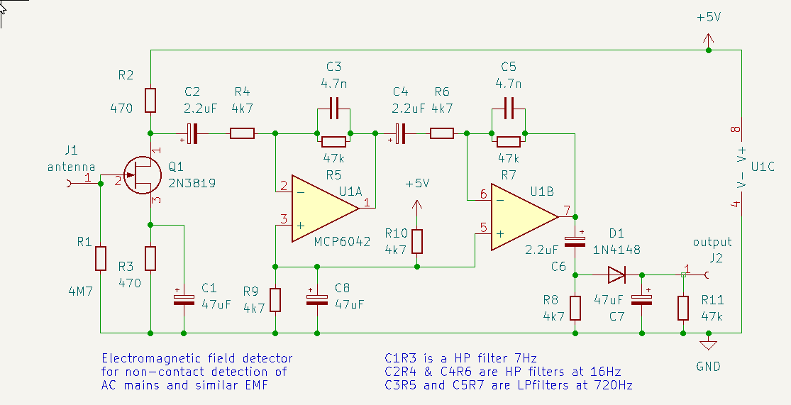
To be CERTAIN and get a true digital response you need to add two things:
firstly a band pass filter - to reject very slowly (static) or quickly (RF) changing signals;
you can easily do this with a simple op amp circuit
and
second, a device that will recognise the presence of a mains frequency SIGNAL, and give a positive response.
thats an easy job for an arduino.
IMHO that's a very similar circuit to the first on on this topic - the brightness of the LED is over current not voltage. Normaly i take a optocoupler between such circuits and the arduino side to be on the save side.
IMHO due to the fact it's done by current and not voltage a band filter will help no further.
Another problem with these high gain amps: When you move the cable or the antenna just a bit results in a wild disco style light show. Ergo: IMHO also not very reliable.
I think these simple types works also analog. I saw a digital one on aliexpress which seems to act digital. There must be a chip somewhere in this wide world...
Good idea. The simple works also analog but i found some in the net with a digital logic. I will order one of those and disassamble. But to find a chip is still the goal...
And the "General Electronics" section is the right place to post about the OP's problem, and using an Arduino to detect the mains voltage. What is your problem?
You dont seem to understand this: the electric field they detect is NOT digital. So you need to
"CONDITION" the signal, then set a level that will be registered as a digital 1 or 0.
This is basically a 1 bit ADC.
ANY digital input pin of an arduino IS a 1 bit ADC.
Signal conditioning in this context is managing the bandwidth to exclude unwanted interference; and applying enough gain to match the very weak signal to the range of the ADC.
I do and you are right, maybe my posts were unclear.
Have you already built the scheme you posted? Looks good. Is this your design or do you have a source? I would like to build that and add a optocoppler or a TTL shifter, i need 3v3.
Yes I've built it and it works but my testing is limited as I dont have a 'scope.
However its very complicated for what it does - mainly because of the need for biasing the op amps.
I'm convinced a simple circuit could be built around a single CMOS hex inverter IC.
A bit like this circuit
Many years ago I designed a bat detector circuit that used VERY few components, based around a HEF4069UBP hex inverter; using the fact that a CMOS hex inverter can be a ( very non-linear) simple amplifier by applying negative feedback.
With a gain of 1000 for three stages, you can build your whole detector circuit with just that one chip and a few external components.