Accurate indoor thermometer with a thermistor, general beginner questions

Greetings everyone, I'm new to Arduino. Been hearing about it a lot in past years but I'm bad at coding almost as I am bad at math so I passed on it, until now.
I decided to start with some very simple projects and one of them is a little harder than I initially thought. Basically it's a room thermometer with 1 thermistor and I already ordered some 1% thermistors from eBay a few days ago (datasheet), while I work on it.
What I would like to achieve is a very accurate thermometer while still remaining simple (in the way of components, not code) and cheap (the price is a matter of principle and is important) but the further that I get along with the planing the more it seems accuracy will become an issue.
This is what I've done so far: Looked at the formulae of the thermistor on Wikipedia, did not understand a thing at first but after a day or two (seriously, told you I'm bad at math) I managed to get them under control. I understand how to calculate resistance/temp from the B value but the datasheet has a 'resistance at different temperatures' table and from it I inferred the A,B and C constants which I found to be more accurate than the B value. The values for the MF2-103 NTC Thermistor are:
A: 0.001107937929960092
B: 0.000238265586603961
C: 6.611377849685053e-8

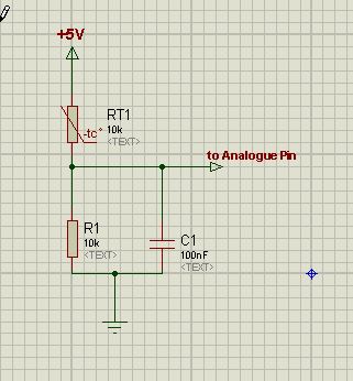
Here is the circuit I plan to make:

Please ignore the zener, I've decided not to put it at all.

So what I plan to do is find the voltage on the ADC pin, calculate the resistance (Rt=39kVt/(12-Vt)) and then use the Steinhart–Hart equation to calculate the temperature, E.G. if Vt is 3v, then Rt=39000*3/(12-3) and T(k)=
1/(0.0011079379299600925+0.00023826558660396095ln(13000)+(6.611377849685053e-8)(ln(13000))^3).
Now for my questions:

  1. Is there a way I can test to see if these thermistors are actually 1% accuracy and not, say, 5% or 10% ? (assume that I don't have a good thermometer, only a (very) cheap DMM)

  2. I was looking for the atmega328p's (and possibly attiny85's) leakage current to the ADC pins but got confused with the results, namely:
    Input impedance of Arduino Uno analog pins? - Electrical Engineering Stack Exchange
    http://www.avrfreaks.net/forum/minumum-current-required-analog-pin-atmega328
    Input Impedance of A0-A5 - General Electronics - Arduino Forum

Is the current 1uA or 50nA? Is it DC? Will a cap really help? Does the sampling rate matter? (I plan on sampling once every few seconds, maybe even as long as a minute)
Because if the current is a constant 1uA I will have to bias for that, 36mV is not negligible.

  1. So far, have I done anything wrong?

Any help will be appreciated!

  1. Do not use a 12V source for the thermistor. You will likely damage the analog input and perhaps even the Arduino. Use 5V or lower.

  2. The input resistance of the ADC is extremely high, but there is a small capacitor that needs to be charged, so maximum recommended input impedance is 10K Ohms. If your thermistor/voltage divider is higher, add a 100 nF capacitor across the input.

  3. For accurate temperature measurements, you will need to calibrate your final circuit using an accurate thermometer.

  4. If you want to have fun and succeed in this hobby, relearn basic math. It is an extremely useful and valuable skill.

Thanks for the quick reply, jremington.

jremington:

  1. Do not use a 12V source for the thermistor. You will likely damage the analog input and perhaps even the Arduino. Use 5V or lower.

According to my calculation, Vt will only exceed 5V when the temperature is 3°C or lower and my logic is that if this will ever happen I will be more concerned about the ensuing nuclear winter than about my thermometer.
I've chosen 12V over 5V for (much) better accuracy.
Of course, all this is true provided that my calculations are correct. Aren't they?

jremington:
2. The input resistance of the ADC is extremely high, but there is a small capacitor that needs to be charged, so maximum recommended input impedance is 10K Ohms. If your thermistor/voltage divider is higher, add a 100 nF capacitor across the input.

Does "across the input" means one side between R1 and R2, and the other connected to the ADC pin? Or does it mean between ADC pin and ground?

jremington:
3. For accurate temperature measurements, you will need to calibrate your final circuit using an accurate thermometer.

Very disappointing. Is there no other way?

Of course, all this is true provided that my calculations are correct. Aren't they?

You did not show your calculations, but you do not gain anything by using 12V.

Or does it mean between ADC pin and ground?

Yes.

Is there no other way?

No. There are several variables (ADC calculation constants, thermistor resistance, resistor value in the voltage divider, reference voltage) that all must be known very accurately for accurate calculation of the temperature. It is best to calibrate against a known standard, as all the professionals do.

Very disappointing. Is there no other way?

You can calibrate with ice water and boiling water. But, I'd kind-of want to check the accuracy at room temperature too. Of course, you'll need to waterproof your thermistor.

The returned A/D value depends on two things.
The voltage on the analogue input, and the A/D reference voltage.

Your 12volt supply might be fairly constant, but is your 5volt line?
If both divider and 5volt supply go up/down the same, A/D value is not changing.
A good reason to supply the termistor voltage divider from the same supply as Aref.

As jremington explained, always use a 100n cap from analogue input to ground.
To lower impedance seen by the analogue input, and to kill hash.

No thermometer is "accurate" untill you calibrate.
Not too hard with an ice-bath and boiling water. Or with a lab thermometer.
A thermistor-type thermometer could be the worse than a TMP35/36 or DS18B20.
Leo..

C4lculated:
Very disappointing. Is there no other way?

Well, yes - since you are in the planning stage. You could change your mind and use a DS18B20 sensor instead. It could turn out to be the best $3 you ever spent. No calibrations required, and no maths either.

C4lculated:
Very disappointing. Is there no other way?

No.
What accuracy do you require ?

If you use Platinum resistance thermometers it is possible to get within 0.1 deg c repeatedly with a properly designed circuit.

Using thermocouples or thermistors will give up to 5 % errors over 0 to 100 deg C easily.

Just replacing the sensor of a calibrated system will cause errors.

EDIT

Cross post

Nick_Pyner:
Well, yes - since you are in the planning stage. You could change your mind and use a DS18B20 sensor instead. It could turn out to be the best $3 you ever spent. No calibrations required, and no maths either.

Much better idea.

jremington:
You did not show your calculations

well, my temp. range is between 3°C to 50°C (37-122 F), so using the thermistor's B-value to calculate R:
10000*(exp(-3950*(1/298.15-1/276.15))) = ~29k.
And then Vt:
(12*29000)/(39000+29000) = 5.1V

jremington:
you do not gain anything by using 12V.

I don't gain greater voltage difference across the thermistor in the 3°C to 50°C range? :confused:

By the way, in case it isn't clear, R2 is the thermistor in my diagram.

If you increase voltage you increase current.
This will cause a self heating effect.

Thermistors are not linear devices and the equations will not give an accurate result without calibration.

Platinum resistance is better in this respect.

What accuracy / precision do you need ?

I don't gain greater voltage difference across the thermistor in the 3°C to 50°C range?

That doesn't help, because you don't have to use the 5V ADC input swing. It may also lead to self-heating. You can use a lower input voltage range, together with a lower, more accurate voltage reference for the ADC and get safe operation over the full 10 bit range.

It is great that you understand the basic principle of the Steinhart-Hart equation, but it is only an approximation. For accurate conversions, the three constants must be individually determined for every single thermistor.

Wow, replies are lightning fast around here.
Thank you all I will now read up on the DS18B20, it is a little too pricey for what I was originally planning (eBay example) but maybe it's worth it.

The freezing/boiling water idea sounds good, I think I'll do it.

Just to clarify, this is a hobby project, nothing professional. I do not have a goal in terms of accuracy, but anything higher than 0.1°C will be disappointing to me.

anything higher than 0.1°C will be disappointing to me.

Accurately measuring temperature is more difficult than you think.

Price some digital thermometers that are guaranteed to be that accurate over the entire temperature range of interest. This one is good to 0.1°C over the range of 18-28 C, but falls off rapidly from there.

C4lculated:
, it is a little too pricey for what I was originally planning (eBay example) but maybe it's worth it.

So you need ten of them, do you?

It's still worth it, and that sort of money should get you one packaged in stainless steel, weatherproof, with 5m of cable and a plug.

Hook up all 10 and average the values! That increases the overall accuracy by a factor of sqrt(10).

Hook up all 10 and average the values! That increases the overall accuracy by a factor of sqrt(10).

And so easy too..........
Now we know the real value of the OneWire library

Wawa:
The returned A/D value depends on two things.
The voltage on the analogue input, and the A/D reference voltage.

Your 12volt supply might be fairly constant, but is your 5volt line?
If both divider and 5volt supply go up/down the same, A/D value is not changing.

Good idea, I'll try to keep my power supplies well regulated.

Boardburner2:
If you increase voltage you increase current.
This will cause a self heating effect.

jremington:
It may also lead to self-heating.

Self heating is a valid point.
in the current circuit, at 3°C the thermistor power will be 0.0008333W, and at 50°C it'll be 0.0002778W. I can't find the rated power in the datasheet, do those values seem to you like they would cause the thermistor to heat?

jremington:
You can use a lower input voltage range, together with a lower, more accurate voltage reference for the ADC and get safe operation over the full 10 bit range.

Can you give me an example of R1, divider voltage and Aref that you think are better?

jremington:
It is great that you understand the basic principle of the Steinhart-Hart equation, but it is only an approximation. For accurate conversions, the three constants must be individually determined for every single thermistor.

Unfortunately, I have no such option.

jremington:
Accurately measuring temperature is more difficult than you think.

It would seem so...

jremington:
Price some digital thermometers that are guaranteed to be that accurate over the entire temperature range of interest.

Where's the fun in that?
Nah, I think I'm committed to this project now, I'm gonna do the best I can with what I have and hope for the best.

Nick_Pyner:
So you need ten of them, do you?

No, I don't need any of them. I want a few extras though for obvious reasons, and 5 cost almost as much as ten.

jremington:
Hook up all 10 and average the values! That increases the overall accuracy by a factor of sqrt(10).

Even though you are kidding, I actually thought of that, but it's too complicated, too bulky and not enough pins.

Still haven't read up on Platinum resistance and the DS18B20, it'll take me a while, English is not my native language so I'm slow on reading/writing.

By the way, thanks to everyone who've helped so far.

C4lculated:
Can you give me an example of R1, divider voltage and Aref that you think are better?

Assuming you use an Uno...
Then you have a 3.3volt supply that is relatively clean/stable, provided it's not used for anything else.
And a stable (not precise) internal 1.1volt Aref.
Might be more stable than a separate 12volt supply and default Aref.
Leo..

Seem to be making a simple ntc circuit very complex, though as said you will not get full range accuracy, but few devices do anyway.

Suggest you first try out your ntc on a working circuit and then develop things from there; this one can give 0.1c accuracy with software improvements.

Below is the circuit and code you need for a basic test jig with the result on the serial monitor

/*

NTC Sensor module with selective Averaging routine.
 
Designed for a 10K thermistor from the Vishay NTCLE100 series,
though generic should be ok.
  
Software calibration correction value to be added
	
November 2015

*/

//  Declare Variables
int AnalogThermPin = A0;   // sensor input pin
int adc = 0;
int adcresult = 0;
float tempC =  0 ;        // result for output
float tempcal  = 0.0;     // the calibration value to add to the temp result


//  set up, start serial monitor
void setup() {
Serial.begin(9600);;
}


void loop() {
 
 adcresult = analogRead(AnalogThermPin);
  
//  Convert Average ADC value to Celcius
//  author: Rolf Widenfelt ; created july 3, 2013
//  +credit to C. Sellers for the Steinhart-Hart equation for the thermistor. 
float resistance = ((1024.0/adcresult) - 1);
float Temp = log(resistance);
Temp = 1 / (0.003354016 + 0.0002569850 * Temp + 0.000002620131 * Temp * Temp + 0.00000006383091 * Temp * Temp * Temp);
Temp = Temp - 273.15;
tempC = Temp;

// Add the ntc calibration value
tempC  = tempC + tempcal;

Serial.print("The temp is: ");
Serial.println(tempC, 1);

delay(5000);              
}

000313.jpg

C4lculated:
Even though you are kidding, I actually thought of that, but it's too complicated, too bulky and not enough pins.

He was kidding, but it wouldn't be that hard in software, the bulk is only in harnessing the final wiring and mounting, and ten DS18B20s take no more pins that one.

Still haven't read up on Platinum resistance and the DS18B20, it'll take me a while,

At the risk of sounding evangelical, the best reading you can do is on reasons why you should not use a DS18B20. The most obvious reasons are

  1. The fastest sensible reading rate at the maximum resolution is once per second

  2. The working temperature range is -25 > 125C

That's about it and, once you have come to terms with those limitations, which I assume would be fairly soon, all that waffle about self-heating, power regulation, divider voltages, reference voltages, calibration, and God only know what all else, disappears into murky void it should have been consigned to long ago.

You will then find that the DS18B20 is extremely popular and very well supported within the Arduino community.

Your English seems to be just fine.