Adafruit_ILI9341 and SPI library issues on GIGA board

@Merlin513 and @BobTheDog - I was curious about the timing differences when the USB is in use and when it is not...

So hooked up Logic Analyzer probes to both USB pins, plus some of the SPI pins, did not do MISO nor DC pin as I wanted some extras to monitor when USB things are being called.

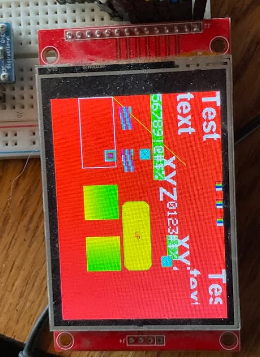
In this case I am using a sketch and device code I was porting over from our Wacom tablet library... This case is the tablet_viewer sketch.

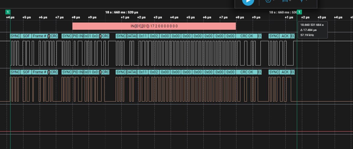
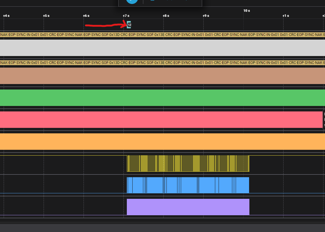
Here is an area of trace when the screen is updated... Which happens if we receive new data from the tablet:

Top two lines are the USB.
The last three are the Display (CS, MOSI, SCK)
The Orange line (channel 3) is the time that an Endpoints call back is being called
Red(2) - is when the USB Task is active
Green(5) - is when the TransferComplete is being processed (Callback from ISR?)

When we zoom out we see that all of our stuff is getting called a lot of the time even though the only time we are actually receiving new data is just in the area of the
area I sort of pointed to:

Also sort of interesting is when you zoom in on receiving one transfer in from the tablet

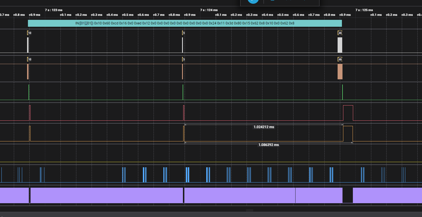
You can see it takes 3 transfer cycles or 2+ms to complete the transfer!
I would have hoped it was all completed within one cycle... Will try to capture something similar with the tabke us connected to something else.

It's called all the time (every ms) because it is an interrupt endpoint, so it is called every USB Frame.

Unless I am misunderstanding?

Sorry it is a Interrupt endpoint. But on the other systems I have worked on, the endpoint code is only called when it actually receives some data...

Maybe there is a timeout as well somewhere, but...

I have a similar setup on TeenyMicromod...
Don't have time right now to set it fully up with bracketing the callbacks.
But on the last part of previous post, here shows it receiving a data packet from the tablet.

More later.

I'm not an USB expert in any way but I think the host has to request a transfer every ms for the Interrupt endpoint?

This is done in the MBED code from the RxHandler in the "driver", called by transfer complete.

I'm not saying it is the best way to do it (I don't think it is) but rather that is how they have done it.

This way of doing it was what was causing the issue I was seeing with the HUB code going bang. I would guess requesting the transfer on the SOF callback would have been a better way of doing it.

Using @KurtE's WIP branch PACMAN seems to working rather well now especially since I have added support for the USB version of a NES controller. Alot simpler controller. Want to verify tomorrow support I have included for the PS4 and PS3 and will probably post a short video on the topic

2 Likes

As promised here is a short video of it using the NES Controller

3 Likes

@Merlin513 - looks like you are having some fun.

I still want to find a way to be able to do asynchronous updates of the display (i.e. DMA), but so far, I still have not found any examples for doing SPI using DMA on the STM32 boards.

For a few minutes, I thought that there might be a solution built into MBED SPI code. (SPIMaster.h)

#if DEVICE_SPI_ASYNCH

    /** Start non-blocking SPI transfer using 8bit buffers.
     *
     * This function locks the deep sleep until any event has occurred.
     *
     * @param tx_buffer The TX buffer with data to be transferred. If NULL is passed,
     *                  the default SPI value is sent.
     * @param tx_length The length of TX buffer in bytes.
     * @param rx_buffer The RX buffer which is used for received data. If NULL is passed,
     *                  received data are ignored.
     * @param rx_length The length of RX buffer in bytes.
     * @param callback  The event callback function.
     * @param event     The event mask of events to modify. @see spi_api.h for SPI events.
     *
     * @return Operation result.
     * @retval 0 If the transfer has started.
     * @retval -1 If SPI peripheral is busy.
     */
    template<typename Type>
    int transfer(const Type *tx_buffer, int tx_length, Type *rx_buffer, int rx_length, const event_callback_t &callback, int event = SPI_EVENT_COMPLETE)
    {
        if (spi_active(&_peripheral->spi)) {
            return queue_transfer(tx_buffer, tx_length, rx_buffer, rx_length, sizeof(Type) * 8, callback, event);
        }
        start_transfer(tx_buffer, tx_length, rx_buffer, rx_length, sizeof(Type) * 8, callback, event);
        return 0;
    }

It looks like the variant is defining the ASYNC:
-DDEVICE_SPI_ASYNCH=1
in the defines.txt.

The transfer function, funnels down to the call:
spi_master_transfer(&_peripheral->spi, tx_buffer, tx_length, rx_buffer, rx_length, bit_width, _irq.entry(), event, _usage);

But I believe the STM implementation:

// asynchronous API
// DMA support for SPI is currently not supported, hence asynchronous SPI does not support high speeds(MHZ range)
void spi_master_transfer(spi_t *obj, const void *tx, size_t tx_length, void *rx, size_t rx_length, uint8_t bit_width, uint32_t handler, uint32_t event, DMAUsage hint)
{
    struct spi_s *spiobj = SPI_S(obj);
    SPI_HandleTypeDef *handle = &(spiobj->handle);

    // TODO: DMA usage is currently ignored
    (void) hint;
...

Now if it were actually implemented, there is no clean way I can see that one can mix and match the uses of the Arduino SPI wrapper class and the underlying MBED SPI class.
Specifically, the Arduino SPI object creates an MBED object, and does not give any way to retrieve that object. Unclear what would happen if I simply created my own MBED SPI object, as it may handle things like control of access...

1 Like

Start of DMASupport -- updateScreenAsync()

As some of you have probably noticed, there does not appear to be any examples of using DMA for SPI on the GIGA and the documentation could use a few minor tweeks :wink:

@Merlin513 found a couple of links that helped :smiley:
microcontroller - Configuring the DMA request multiplexer on a STM32H7 MCU - Electrical Engineering Stack Exchange

Using the STM32F2, STM32F4 and STM32F7 Series DMA controller (adammunich.com)

With that, I was finally able get a test sketch to update the screen using DMA to work. It was hard coded to use DMA1_Stream1 and the like.

Was running into an issue, that some of the screen was showing garbage.... We were able to confirm that it was a DMA cache issue, which he found some information to validate this up at:

Which appears to have been fixed by adding a call:
SCB_CleanInvalidateDCache_by_Addr( _pfbtft, CBALLOC);

This morning, I then integrated the code into my port to the GIGA of my library ILI9341_t3n.

Currently the DMA support is in a branch, that I am testing, need to disable a bunch of the debug code and some more testing...

KurtE/ILI9341_GIGA_n at dma_support (github.com)

Test sketch I use for debugging and testing Frame buffer DMA...

That was output using the DMA.

Now back to playing

2 Likes

Since I am as much of gluten for punishment I wanted to see how the DMA transfers would perform. So I ported over my TeensyOpenGL library to Giga and ran one of test high res graphics sketches:

Doesnt work too bad. Now to figure out how to get the M7 process to go faster than 240Mhz :slight_smile:

1 Like

Quick update:
Merged the DMA stuff back into main branch.
I have done some testing of the code, that now appears to work for two displays
I have them on each SPI (SPI and SPI1), Simple test works for updating both of them at the same time.

#include <LibPrintf.h>
#include <elapsedMillis.h>
#include <ILI9341_GIGA_n.h>
#include <ili9341_GIGA_n_font_Arial.h>
#include <ili9341_GIGA_n_font_ArialBold.h>

REDIRECT_STDOUT_TO(Serial)

// BUGBUG:: For now use libprintf

#define TFT_DC 9
#define TFT_RST 8
#define TFT_CS 7
ILI9341_GIGA_n tft(&SPI1, TFT_CS, TFT_DC, TFT_RST);
#define TFT2_DC 24
#define TFT2_RST 26
#define TFT2_CS 22
ILI9341_GIGA_n tft2(&SPI, TFT2_CS, TFT2_DC, TFT2_RST, DMA1_Stream3);

uint16_t colors[] = { ILI9341_RED, ILI9341_BLUE, ILI9341_GREEN, ILI9341_WHITE, ILI9341_YELLOW};
#define CNT_COLORS (sizeof(colors) / sizeof(colors[0]))


void setup() {
  Serial.begin(115200);
  while(!Serial && millis() < 5000) {}
  Serial.println("\n*** Dual TFT test ***");
  Serial.println("Start TFT");

  tft.begin();
  tft.setRotation(1);
  for (uint8_t i = 0; i < CNT_COLORS; i++) {
    tft.fillScreen(colors[i]);
    delay(500);
  }

  Serial.println("Start TFT2");
  tft2.begin();
  tft2.setRotation(1);
  for (uint8_t i = 0; i < CNT_COLORS; i++) {
    tft2.fillScreen(colors[i]);
    delay(500);
  }

  tft.useFrameBuffer(true);
  for (int i = CNT_COLORS - 1; i >= 0; i--) {
    tft.fillScreen(colors[i]);
    tft.updateScreen();
    delay(500);
  }

  tft2.useFrameBuffer(true);
  for (int i = CNT_COLORS - 1; i >= 0; i--) {
    tft2.fillScreen(colors[i]);
    tft2.updateScreen();
    delay(500);
  }
  tft.setFont(Arial_20_Bold);
  tft.setTextColor(ILI9341_BLACK);
  tft2.setFont(Arial_20_Bold);
  tft2.setTextColor(ILI9341_BLACK);
}

void loop() {
  elapsedMicros em;
  uint32_t delta_time_not_dma = 0;
  uint32_t delta_time_dma = 0;

  for (uint8_t i = 0; i < CNT_COLORS; i++) {
    em = 0;
    tft.fillScreen(colors[i]);
    tft.setCursor(ILI9341_GIGA_n::CENTER, ILI9341_GIGA_n::CENTER);
    tft.print("Direct");
    tft.updateScreen();
    tft2.fillScreen(colors[i]);
    tft2.setCursor(ILI9341_GIGA_n::CENTER, ILI9341_GIGA_n::CENTER);
    tft2.print("Direct");
    tft2.updateScreen();
    delta_time_not_dma += em;
    delay(500);
  }

  for (int i = CNT_COLORS - 1; i >= 0; i--) {
    em = 0;
    tft.fillScreen(colors[i]);
    tft.setCursor(ILI9341_GIGA_n::CENTER, ILI9341_GIGA_n::CENTER);
![IMG_1813|500x375](upload://bG7q0TYB2VRxx9iQNXCIo2Sx5jE.gif)
    tft.print("DMA");
    tft.updateScreenAsync();
    tft2.fillScreen(colors[i]);
    tft2.setCursor(ILI9341_GIGA_n::CENTER, ILI9341_GIGA_n::CENTER);
    tft2.print("DMA");
    tft2.updateScreenAsync();
    while (tft.asyncUpdateActive() || tft.asyncUpdateActive()) {}
    delta_time_dma += em;
    delay(500);
  }
  Serial.print(delta_time_not_dma, DEC);
  Serial.print(" ");
  Serial.println(delta_time_dma, DEC);

}

I have also implemented the continuous dma update mode and callbacks, which appears to work with my FB and Clip test sketch (example with library)

For the fun of it it, I made a version of the uncanny eyes we have running on a Teensy, with ST7735/ST7789 to work with ILI9341...

It is working with one eye, but two eyes I get the blinking red led crash...
Sorry for the poor-quality GIF file, I just did a quick live vew photo with my camera and then converted to GIF.

IMG_1813

Sort of fun :smiley:

1 Like

Two Eyes
IMG_1814

I have not tried to do stuff in here yet to mirror one eye...
More a test to see if I can get two displays to work at the same time.

With my wiring and breadboard, I needed to slow the SPI down to 20mhz.
But looks like it is still outputting something like 20 frames per second.

2 Likes

Nice job!!! Looks strange using the big displays instead of the ST7789's

1 Like

I have been trying to get this library to work now for a while, is it still functioning?

I do get the display to run the graphicstest with the regular adafruit ili9341 library so I think my wiring is correct. But it is updating very slow, even if setting a higher frequency in the begin method.

However when i try the ILI9341_GIGA_n library I do get it to compile and run but the screen only goes white. I tried passing both SPI and SPI1 in the constructor without any difference. Any ideas what I'm doing wrong? The screen I have says it's driver is ili9341v but the adafruit ili9341 library works fine(except the speed), if that matters.

This works with the adafruit library:

#define TFT_DC 9
#define TFT_CS 10

Adafruit_ILI9341 tft = Adafruit_ILI9341(TFT_CS, TFT_DC);

This is from the graphicstest example in the ILI9341_GIGA_n repo and does not work:

#define TFT_DC 9
#define TFT_RST 8
#define TFT_CS 10
#define USE_FRAME_BUFFER 1

ILI9341_GIGA_n tft(&SPI1, TFT_CS, TFT_DC, TFT_RST);

#define DEBUG_PIN 0

I have the screen connected to the 6pin SPI header, but I tried the other one at pin 11,12,13 to without success.

Anyone? I’m starting to rip my hair out

This looks like it is setup for pins at 11-13 as that is SPI1
There is the confussion, that:
Arduino SPI object uses the hardware spi1 object
and the SPI1 object uses the spi5 hardware object...

I have had my ILI... library working recently as I have also been playing with
zephyr version of the GIGA setup... I just pushed up current stuff with
zephyr stuff, but it is in the zephyr branch. Again only WIP or more PIP
KurtE/ILI9341_GIGA_n at zephyr

Thanks for getting back!

I did try with both passing SPI and SPI1 in the constructor and tried both pins 11-13 and the 6 pin header in all combinations.

However I have gotten it to work now (sort of) so I know my wiring and setup is correct. It is a lot faster, awesome!

But when ever I kill the power to the board (unplugging the usb) and plug it back in again I get a white screen even though the sketch is running. I think this is probably the reason why I only got a white screen when trying all combinations of pins and SPI objects.

When ever I get a white screen, I can upload the adafruit ili9341 library graphics test from the arduino IDE and then the screen starts working again, and after that I can upload the graphics test from your library and runs fast and nice. But again after every power off/on I need to upload the adafruit library again so make the screen work.

My screen doesn't have a reset pin, could it be a problem with the screen not reseting properly?

I did try to replace the initcmd in your library with the one init_commands from the adafruit library but that did not make any difference.

Any ideas what the problem could be?

Sorry, it may take me a little time before I can debug this.
My guess is that some state of the SPI registers are not being cleared out when it reboots or the like, maybe will have to try some hard setting/clearing of registers in my begin method.

I usually almost always use a hardware reset pin, as to hopefully help make sure the display can be in some known state. Sometimes you can hack it by having it on the
processors reset pin, so when the processor resets, so does the display.

Not sure I have tried that on some of these boards.

Ok! I did try to send the software reset command as the adafruit library does and then wait for 150ms but that made no difference. I ”solved” it for now by dynamically allocating an object of the adafruit library, call the begin method, and then delete the object. After that I can call begin() from your library and that does the trick.

I added some support now for this in the main branch.

Note however, depending on which display you are using, there are issues if you do not connect the reset pin on the display.

That is if you are using a display from Adafruit, like:
3.2 TFT LCD with Touchscreen Breakout Board w/MicroSD Socket [ILI9341] : ID 1743 : Adafruit Industries, Unique & fun DIY electronics and kits
It should work if you don't hook up the rest pin:
image

However if you are using many of the others, for example like the ones sold by PJRC
PJRC Store
Or similar ones you can order from Amazon.com or Ebay.com... That look like:

Then you normally need to either wire the reset pin to an IO pin that you
pass into the library OR wire it to 3.3v as shown on the PJRC web page mentioned
just above.

Why, these displays do not wire up the reset pin to anything and leave it floating.
And if the pin reads as a low state, the display will be left in a reset state.