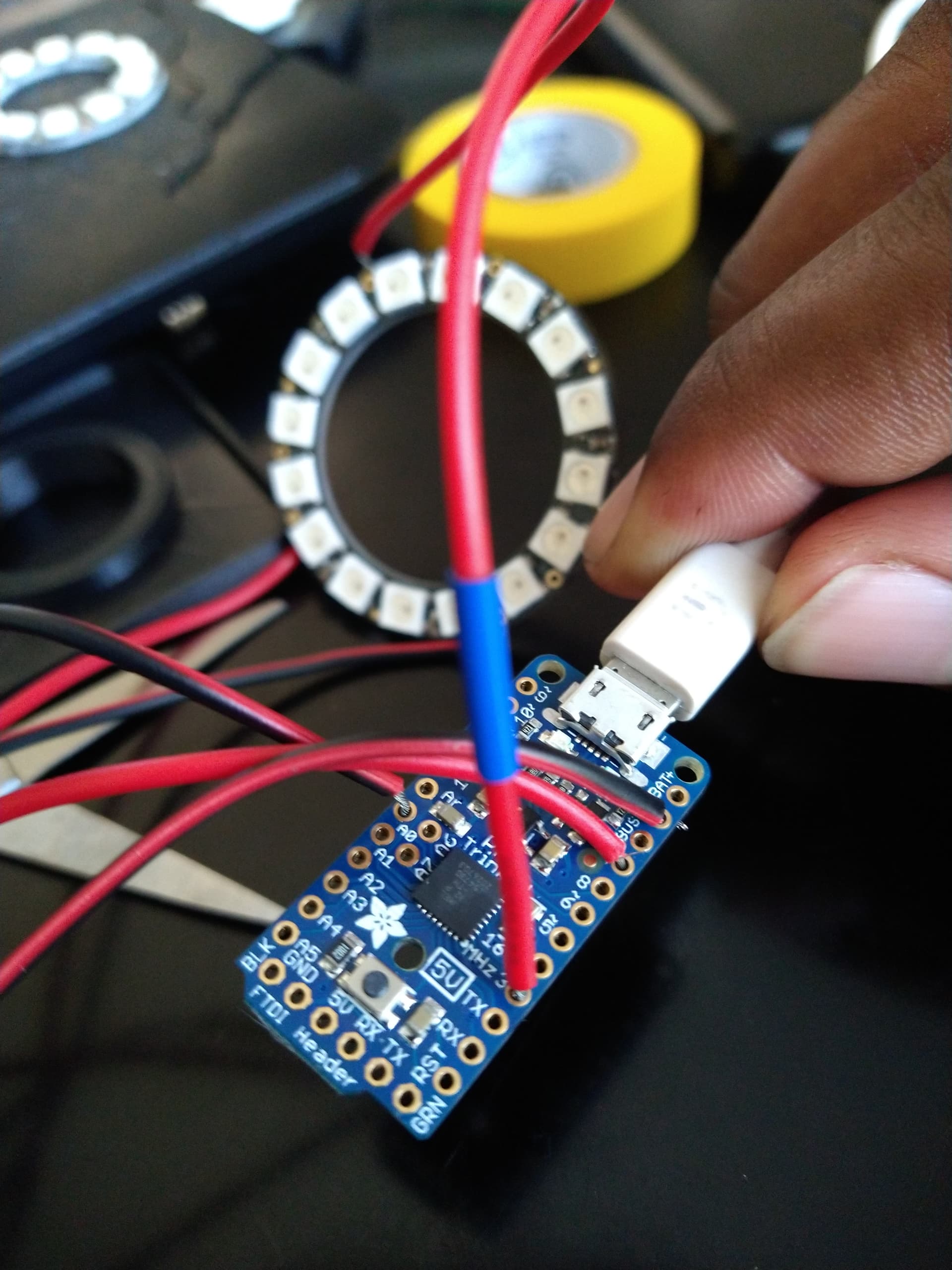
This is my first post and I've been wanting to use these Neopixel Ring Lights for quite a long time, and it was inspired by a video on YouTube by I Like To Make Stuff (GoPro Ring Light. I am using the Adafruit Pro Trinket for this setup since it was easy to get.
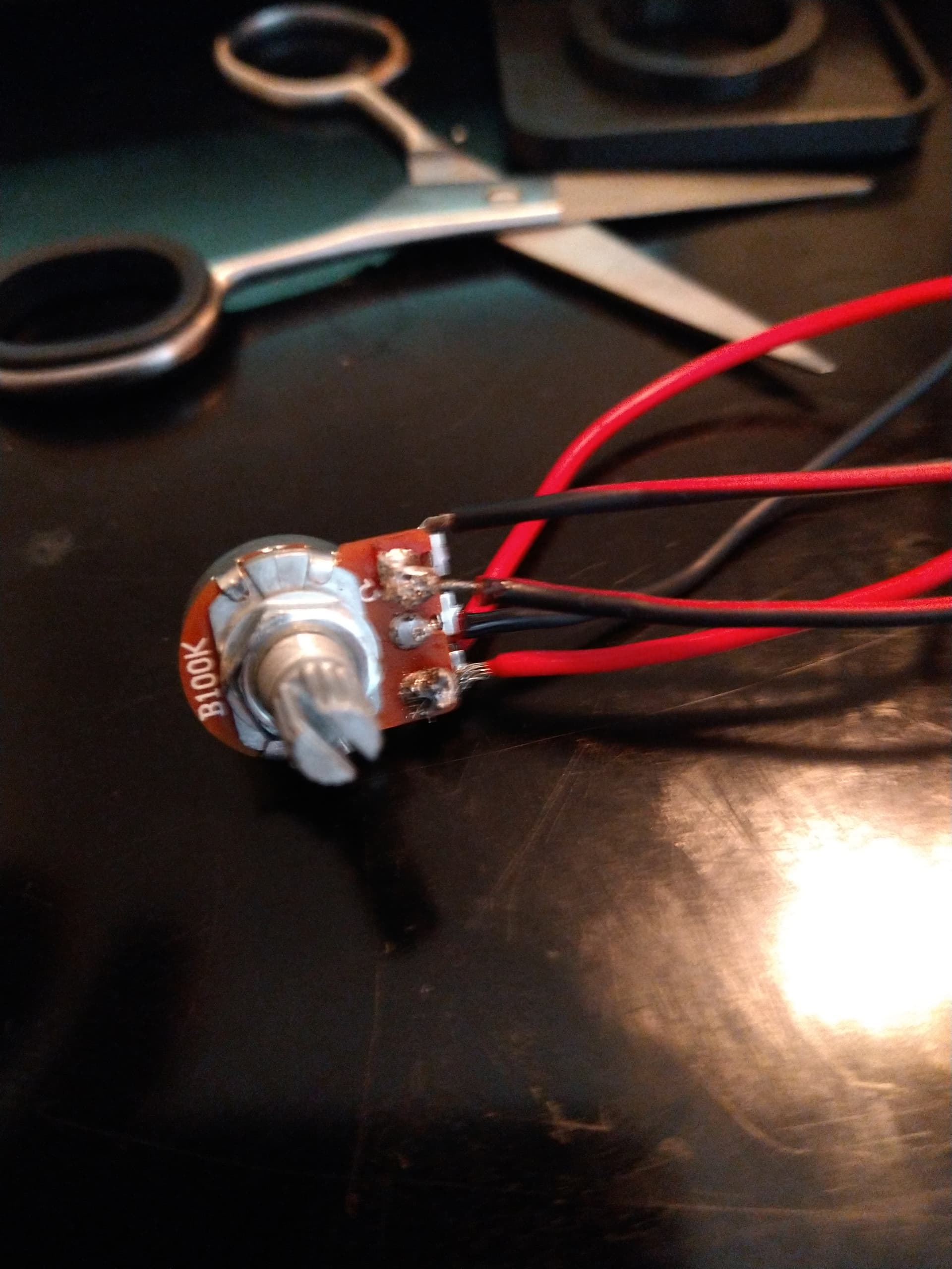
I am designing a light for a HMC, and after doing all of the proper connections, including setting up the correct pins, the light works well, but the potentiometer won't even dim the lights. Below is the code for the light (it was modified by Bob so it would work with a potentiometer. I'm using The Neopixel 16 Ring Light (bright as hell btw)
//Modified by Bob Clagett for use with the project at http://www.iliketomakestuff.com/make-gopro-ring-light

// NeoPixel Ring simple sketch (c) 2013 Shae Erisson
// released under the GPLv3 license to match the rest of the AdaFruit NeoPixel library

#include <Adafruit_NeoPixel.h>
#ifdef __AVR__
  #include <avr/power.h>
#endif

// Which pin on the Arduino is connected to the NeoPixels?
// On a Trinket or Gemma we suggest changing this to 1
#define PIN            6

// How many NeoPixels are attached to the Arduino?
#define NUMPIXELS      16
// When we setup the NeoPixel library, we tell it how many pixels, and which pin to use to send signals.
// Note that for older NeoPixel strips you might need to change the third parameter--see the strandtest
// example for more information on possible values.
Adafruit_NeoPixel pixels = Adafruit_NeoPixel(NUMPIXELS, PIN, NEO_GRB + NEO_KHZ800);

int delayval = 20; // delay for half a second
int potPin  =   3;  //analog pin used for potentiometer

void setup() {
  // This is for Trinket 5V 16MHz, you can remove these three lines if you are not using a Trinket
#if defined (__AVR_ATtiny85__)
  if (F_CPU == 16000000) clock_prescale_set(clock_div_1);
#endif
  // End of trinket special code

  pixels.begin(); // This initializes the NeoPixel library.
}

void loop() {

  // For a set of NeoPixels the first NeoPixel is 0, second is 1, all the way up to the count of pixels minus one.
int sensorValue = analogRead(potPin);
int brightnessVal = map(sensorValue, 0, 1023, 0, 255);
  for(int i=0;i<NUMPIXELS;i++){

    // pixels.Color takes RGB values, from 0,0,0 up to 255,255,255
    pixels.setPixelColor(i, pixels.Color(255,255,255)); // Moderately bright green color.

    pixels.show(); // This sends the updated pixel color to the hardware.

    delay(delayval); // Delay for a period of time (in milliseconds).

  }
}
Any particular reason why the dial isn't dimming the light as it should? I've been changing pins, resoldering wires to make sure its correct, but no avail. Thank you
void loop() {

  // For a set of NeoPixels the first NeoPixel is 0, second is 1, all the way up to the count of pixels minus one.
int sensorValue = analogRead(potPin);
int brightnessVal = map(sensorValue, 0, 1023, 0, 255);
  for(int i=0;i<NUMPIXELS;i++){
     // pixels.setBrightness sets the  brightness of the strip.

    pixels.setBrightness(brightnessVal);

    // pixels.Color takes RGB values, from 0,0,0 up to 255,255,255

    pixels.setPixelColor(i, pixels.Color(255,255,255)); // Moderately bright green color.

    pixels.show(); // This sends the updated pixel color to the hardware.

    delay(delayval); // Delay for a period of time (in milliseconds).

  }
}
This will help you unserstand the uses of the library commands.
Unfortunately, that option is greyed out. I'm on Windows 10 using a USB 3.0 input (I later learned that these are kinda flaky with the pro trinket) and waiting for a USB 2.0 Hub.
I made sure to connect the middle wire from the potentiometer to header A0
There is no Serial-to-USB chip onboard. This is to keep the Pro Trinket small and inexpensive, you can use any FTDI cable to connect to the FTDI port for a Serial connection. The USB connection is for uploading new code only.
I guess that's why they called it "Pro" trinket. Pro == unsuitable for beginners.
It's not very helpful unfortunately... thankfully, the light turns on, and I can just print up a diffuser for now. I might also change the potentiometer to a 20K (using a 100k model for testing)
Interesting. Because I was following that video on YouTube and he had this exact setup, even with multiple wires.
I've already removed these wires and I'm going to attempt to set it up differently, such as connecting the wires from the Neopixel to the board and figure out how to get the potentiometer as a middle man
And I think you just helped me solve why the dimmer isn't working. I have the GND wires where the 5V should be and vice versa. If I reverse these connections, the dimmer should work.