In Arduino Mega, I have implemented a voltage meter for a 3.7v Li-Ion battery which is unstable because the ADC fluctuates between 150-154. How can I avoid this fluctuation? Just averaging the readings?
Tried using 0.1uF capacitors between analog port A6 and GND, and between the 5V pin and GND, but no change observed.
Thank you!
// Define analog input
#define ANALOG_IN_PIN A6

// Floats for ADC voltage & Input voltage
float adc_voltage = 0.0;
float in_voltage = 0.0;

// Floats for resistor values in divider (in ohms)
float R1 = 30000.0;
float R2 = 7500.0;

// Float for Reference Voltage
float ref_voltage = 5.0;

// Integer for ADC value
int adc_value = 0;

void setup()
{
   // Setup Serial Monitor
   Serial.begin(9600);
   Serial.println("DC Voltage Test");
}

void loop(){
   // Read the Analog Input
   adc_value = analogRead(ANALOG_IN_PIN);

   // Determine voltage at ADC input
   adc_voltage  = (adc_value * ref_voltage) / 1024.0;

   // Calculate voltage at divider input
   in_voltage = adc_voltage / (R2/(R1+R2)) ;

   // Print results to Serial Monitor to 2 decimal places
  Serial.print("Input Voltage = ");
  Serial.println(in_voltage, 2);
  Serial.println(adc_value);

  delay(1000);
}
0.01uF or 0.1uF? Your wiring diagram shows the former, your text says the latter.
Also, from the "Analog Input Circuitry" section of the ATmega2560 datasheet:
The ADC is optimized for analog signals with an output impedance of approximately 10K or less. If such a source is used, the sampling time will be negligible. If a source with higher impedance is used, the sampling time will depend on how long time the source needs to charge the S/H capacitor, which can vary widely. The user is recommended to only use low impedant sources with slowly varying signals, since this minimizes the required charge transfer to the S/H capacitor.
Given that, you might want to try reducing your resistors to 10K and 2.5K.
Also, rather than using the default 5V reference, a more stable voltage reference (either one of the internal references or a well bypassed external voltage on the AREF pin) can help.
I made a mistake with the value of the capacitor in the initial diagram, I've already corrected it.
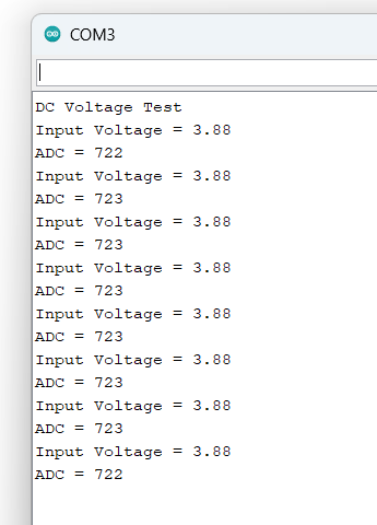
I changed the resistor values and used the 1.1V reference voltage. Now, the ADC fluctuation is minimal, ranging between 723 and 721 initially, and then stabilizing to 722-723.
Thank you! I replaced the 0.1uF with 22uF (I don't have a 10uF on hand) and there was no major difference after changing the internal voltage from 5V to 1.1V, as well as the resistors.
No, the only components I have connected for this test are the Arduino Mega, the voltage divider, the battery, and a 0.1uF capacitor as indicated in my diagram. The length of the cables is 10cm.
I'm going to see what happens now that I integrate this into the main circuit.
About the accuracy of the ADC: the datasheet specifies an absolute accuracy of 3 LSB. That means that a reading of 151 really means: 151 +/- 3, so readings from 148 to 154 are within spec.
If you’d connect the battery directly to the input pin, as suggested in post#5, the reading might be around 750 (meaning 750 +/- 3), improving the accuracy of the total system 5 fold. However, this introduces a problem if the battery is connected and the supply voltage is switched off.
Another problem is the reference voltage. The supply from your PC is used not only to power your board, but also as reference voltage for the ADC. From my PC I’ve seen voltages as high as 5.1V and as low as 4.5V. That means that calibration is necessary.
The schematics in post#1 suggest using the internal reference of 1.1V. The datasheet specifies this as 1.0V to 1.2V. Here calibration is necessary too.
One possibility is connecting the battery with a 10k resistor in series to your input A6. This resistor is high enough to protect the input pin, but will not affect the measurement; there will be drain on the battery with the board supply off, not with supply on. I suggest to use the 3V3 output for calibration, that regulator is specified as 1%. The 3V3 can be connected to A7directly, in which case the formula is: voltageBattery = 3.3 * adcResultA6 / adcResultA7 .
You may also use a voltage reference such as the TL431, that is available with 0.5%, 1% or 2% accuracy. The formula becomes: 2.5 * adcResultA6 / adcResultA7 .
If you’re using the battery that is measured for powering your board, bear in mind that the board alone may consume as much as 50mA.
Thank you so much for such detailed feedback! I did it just as you commented. I connected the battery to port A6 through a 10K resistor, and to A7, the 3.3v for calibration. Additionally, I set the internal reference voltage to 5v, and it worked wonderfully for me.
PD: Sorry for my delayed reply, I had an authorization issue with my account that Arduino has already resolved.