Copilot recommended a single threshold with debounce for detection but I realize that is throwing data away. So I will use 2 thresholds, a higher initial threshold and a lower qualified threshold.
Once the signal drops below the initial threshold, I start counting, once above, I stop. If the qualifier threshold is met, then I know the car passed overhead. I can use the count of cycles to determine speed of the 2.5 inch car. (I get ms per inch and then convert to mph.)
A photo transistor is generally a more direct replacement for a LDR. A photo diode is more difficult to use. Infrared proximity sensors may also be useful for object detection and possibly more reliable than using just disturbances to the ambient light.
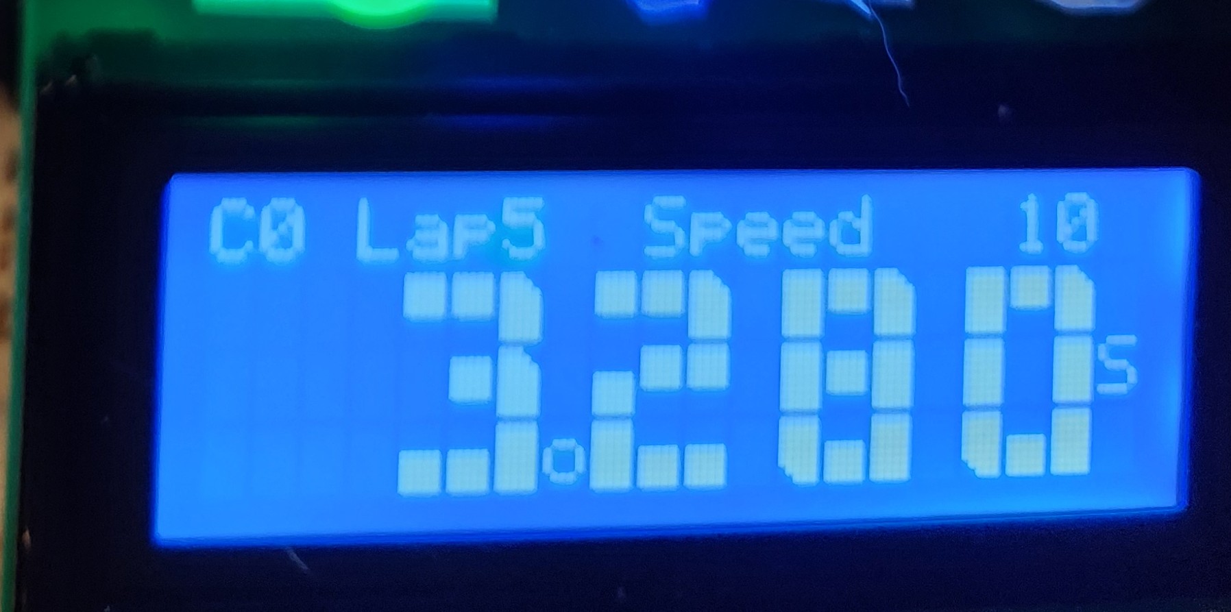
My trap speed detector is now working great, generates mph as expected.
In essence, I measure the number of ADC conversions per millisecond which is 36. If I have two lanes, then it's 18 per second. I count the conversions and send that down into the ring buffer for the main loop to do the floating point.
However for the most part, I try to do all my math as integer based.
So instead of x *= 0.75: I do: x=(x*3) >> 2;
I have the code on GitHub as a public project. Still a work in progress. I will post the link when I'm further along. If you pm me, I'll send a link. (pm allowed here?)
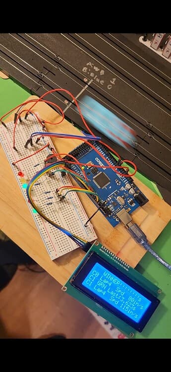
Notice no light gantry is needed, I bought a floor lamp that shines much needed light above the table. With my two threshold measuring technique, no false positives from shadows.
I’ve read only post #1.
Your ADC will run at 1MHz, resulting in 76k measurements per second. This is too fast.
Normal in Arduino is Division Factor 128 to achieve a clock speed of 125kHz, resulting in 9600 measurements per second.
@stitech, it can read faster than 9600 per second but not as high as I am requesting.
Indeed, I need to calm that setting down as I'm currently getting 36 reads per millisecond, so 36000 per second. The while not ready loop, waits for the ADC to be ready. (This might actually be 38.5KHz giving the rounding)
I’ve been thinking about speed again.
Assume source resistance 10k, S/H capacitor = 14pF, RC time = 0.14us.
At ADC_clock = 1MHz, time for charging the S/H capacitor is: 2us.
This should be enough.
The other problem is minimizing the execution time of the ISR.
After the interrupt occurs, the current instruction is finished, a delay of 1 or 2 cycles.
Then a jump to the ISR, 3 cycles.
The ISR will at least PUSH and POP r0, r1 and status register, so at least 20 cycles overhead.
The ISR below will use at least 2 working registers, the compiler will add PUSHes and POPs for those, another 8 cycles gone.
The branch takes 1 or 2 cycles, 2 registers are read and 1 written, say 8 cycles.
Total: 41 cycles = 2.5us.
This leaves some room for operations on the results, but be careful that you leave enough time for the execution of loop().
Fastest ISR for ADC: {  // if longer than 13us, input selection will have changed
  // ADIF is reset by hardware
  uint8_t tmp = ADCH;             // make local variable
  if (ADMUX & 0b00000001 == 0) {  // ADMUX as memory, value belongs to selected input
    ADMUX = 0b00100001;           // set for input A1, keep ADLAR, don't read-modify-write
    // operations on tmp here, mind execution time
    x0 = tmp;                     // don't use indexing, memory access only once
  } else {
    // input A1 was read
    ADMUX = 0b00100000;  // set for input A0, keep ADLAR
    // put the same operations here if needed, only one brach will be executed
    x1 = tmp;            // memory access only once
  }
}
The datasheet of the ATmega2560 gives a maximum clock speed for the ADC of 1MHz, in which case 1 conversion takes 13μs.
If a new input is selected while a conversion is running, it is delayed till the current conversion is complete.
You’ve got 13μs to read the result of a conversion before it is overwritten, and you can’t be sure which input your result came from.
Your sketch doesn’t compile, many things are not declared.
Why setup() in a Class?
In your ISR I see many things that take unnecessary time. static uint8_t accCount=0;
The initialization at the first time needs a variable as switch, this must be read from RAM (a working register must be freed by a PUSH), followed by a test and a branch. Then the variable itself must be read from RAM. sensor=sensors[curSensor];
The base of the table will be read from RAM. The index will be read from RAM and added. Then the value itself will be read from RAM. (Not every variable needs a new working register freed by a PUSH, the compiler will reuse whenever possible.) while(!(ADCSRA & (1 << ADIF))) {
The Interrupt Flag is reset by hardware when the interrupt is executed, so it’s always 0, but as it is it takes a read, an operation and a branch.
And the list goes on, you'll never make it in 13μs.
Btw, my project is very big, I only gave the code for ISR.h
76923 analog reads per second isn't happening now. My actual throughput is half that and the sketch is working very well noticing the car, so I should reduce the sampling rate.
This is perhaps the most important line of code, without it, everything goes to gibberish. This limits the rate to what it can actually do. while(!(ADCSRA & (1 << ADIF))) {}
Interesting tidbit I discovered, halving the scaler cuts the samples per second in half. So if the interrupt was too slow, it wouldn't be linear like that.
Well here is my project page. Introducing Vroom Racer.
The project is playing testing well.
It has lane rider protection (when a car hops on your lane), automatic yellow flag, automatic red flag and even a competition yellow about halfway through the race.