Adding Arduino to Miniature Kit LEDs

I am trying to add an Arduino Micro to a miniature kit that included 7 LEDs. The kit included a battery pack with 3x AA batteries to power the LEDs. Unfortunately, I have no information on the specs of the LEDs.

Id like to essentially turn the kit into a nightlight. Id be using a photo-resistor (LDR) to detect light amounts and if dark, the LEDs turn on.

I have attempted to connect the 7 LEDs in parallel to the Arduino while powered via USB, however the LEDs did not come on when a loss of light was detected.

This led to much troubleshooting.

I confirmed everything (Code, Physical wiring, correct pins etc..) worked with another kit I have that includes only 3 LEDs.

To confirm the LEDs worked and in the chance the Arduino was not able to power the 7 LEDs, I powered them via 3x AA batteries directly. The LEDs come on at full brightness.

I then attempted to have the 7 LEDs powered via the 3x AA Batteries and the LDR powered by the Arduino/USB. I get the same result, LEDs do not power with a loss of light.

Serial monitor indicates the LDR is working as expected.

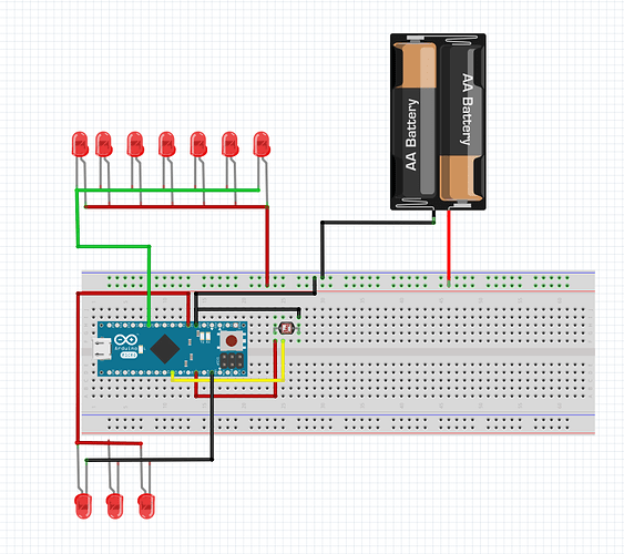
In the diagram attached, I have both the 3 LED Miniature house, and the 7 LED Miniature house drawn. Ultimately, this is what I would be going for. I have attempted to isolate each as described above to work out what is going wrong.

To reiterate the Arduino is connected via USB power to a PC. The 3xAA Batteries would be used only to power the 7 LEDs when light is low.

Here is the code I am using:

const int ldrPin = A5;   // Photoresistor connected to analog pin A5
const int ledPin = 2;    // LED connected to digital pin 2
const int ledPin2 = 7;    // LED connected to digital pin 3
const int threshold = 250; // Threshold for light level detection
const int hysteresis = 20; // Hysteresis value to prevent rapid toggling
bool ledState = false;   // Track the LED state

void setup() {
  pinMode(ldrPin, INPUT); // Set the LDR pin as INPUT
  pinMode(ledPin, OUTPUT); // Set the LED pin as OUTPUT
  
  pinMode(ledPin2, OUTPUT); // Set the LED pin as OUTPUT

  digitalWrite(ledPin, LOW); // Turn off the LED initially
  digitalWrite(ledPin2, LOW); // Turn off the LED initially
  Serial.begin(9600); // Initialize serial communication for debugging (optional)
}

void loop() {
  int lightLevel = analogRead(ldrPin);
    Serial.println(lightLevel); // Print a message (optional)
  if (lightLevel < (threshold - hysteresis) && !ledState) {
    digitalWrite(ledPin, HIGH); // Turn on the LED when it's dark
        digitalWrite(ledPin2, HIGH); // Turn on the LED when it's dark
    Serial.println("Darkness Detected!"); // Print a message (optional)
    ledState = true; // Update the LED state
  } else if (lightLevel > (threshold + hysteresis) && ledState) {
    digitalWrite(ledPin, LOW); // Turn off the LED when there is light
        digitalWrite(ledPin2, LOW); // Turn off the LED when there is light
    ledState = false; // Update the LED state
  }

  delay(100); // Delay to prevent rapid LED toggling
}

Any help on what I'm missing or doing wrong would be great.
Use a transistor driver for the LEDs.

Simple LEDs require a series dropping resistor.

The photo resistor requires a series resistor, probably 10k.

1 Like

Thank you for the input.

To eliminate the photo-resistor from a possible issue Ive removed it from the project for now.

const int ledPin = 7; // Pin number for the LED

void setup() {
  pinMode(ledPin, OUTPUT); // Set the LED pin as OUTPUT
}

void loop() {
  digitalWrite(ledPin, HIGH); // Turn on the LED
}

As I dont have the specs for the LEDs I tried various resistors (100, 220, 330, and 10k ohm) on the LEDs with no luck.

I have also tried this setup on an Uno and a different breadboard and get the same result.

If I plug the lights directly to the Batteries, I get power and lights. If I add a resistor, I do not get power, even when directly connected.

Hi,
If you are using parallel set of LEDs then they will be drawing more current than the controller output pins supply, you may even damage the controller output pin.

You need to add a switching BJT or MOSFET for the controller to send its signal to, the BJT or MOSFET will then switch the higher current needed to control your LED strips.

Tom... :grinning: :+1: :coffee: :australia:

1 Like

You'll need one resistor per LED.

The current through a LED will be (Vcc - Vf) / R; e.g. (5 - 2) / 330 = 9 mA.

As mentioned, the safe current on a pin (for your microcontroller) is 20 mA; so you can put two in parallel on one pin at maximum. So you can possibly split your LEDs in groups of 2.

Your next hurdle is the maximum current per port (that is a group of (up to) 8 pins; consult the datasheet of the 32U4 microcontroller and the schematic of the Arduino Micro); this maximum is 100 mA.

Lastly there is a maximum of 200 mA through the GND and Vcc lines of the microcontroller (not the board).

One solution is to use multiple pins on the Arduino (taking into account the above limits). The alternative is, as mentioned, use of a transistor or mosfet; one transistor / mosfet will do but if you ever have a need to control each LED individually you will need to use a transistor / mosfet per LED (and you still need a resistor per LED).

You need more details on how to run your specific LEDs.

Also if you run this from a battery pack, it won't be working for many nights... you can improve a bit by using sleep modes on your Arduino but that's still going to be just a few nights. You may better use a spare USB phone charger and power it that way.

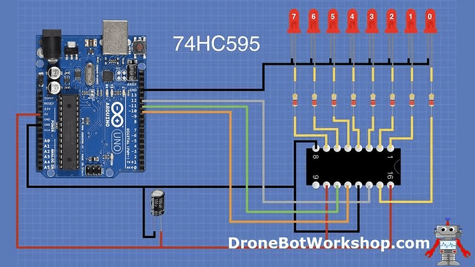
Try using a shift register... needs three signal pins, but I would use external 5V power.
https://dronebotworkshop.com/shift-registers/

I appreciate all the feedback. The biggest issue I had with all the suggestions was the idea that this was a pre-built off-the shelf miniature kit intended to run directly off of the 2xAA batteries as is.

I took a step further back and tried each led individually and of the 7, 6 worked as expected. 1 of the 7 however did not power on and actually caused the wire to get hot and begin to smoke.

Pulling that led out of the circuit, I can now power the LEDs as from the arduino with USB power. Ive added the photo resistor back and it also works when light is below a threshold.

Thanks again everyone it lead me to take a step back and start from step 1.

Hi, @mewastingtime

What are you using as a power supply?
If its a Lipo, why haven't you got a fuse in the line?

Can you please post some picture of you project?
So we can see your component layout.

Tom... :grinning: :+1: :coffee: :australia:

You burned out that LED because you did not have a current limiting resistor in your original circuit

LEDs normally fail open, not closed - in a way acting as a fuse.
Smoking wires is indicative of a short. The LED in question may still be perfectly fine.

This topic was automatically closed 180 days after the last reply. New replies are no longer allowed.