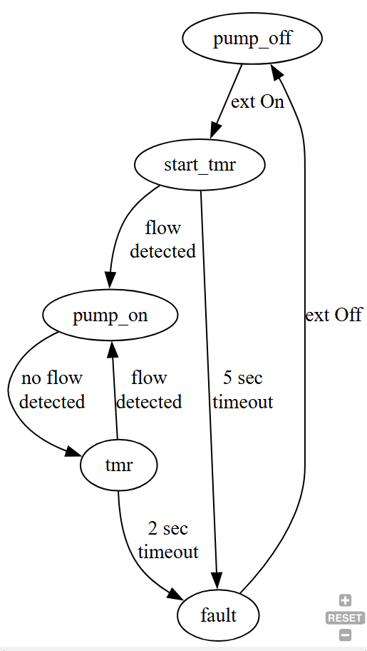
The idea for above is to determine if the flow switches indicate good flow (after the initial 5 second keep the out1 HIGH to allow system to stabilize), and if so make the output HIGH (out1) to keep the relay board energized which in turn keeps the separate latching relay circuit closed which keeps pump working. If any flow switch opens for more than 2.5 seconds, make out1 LOW to de-energize relay board and thus pump.
Yes, correct. out1 is the output from the Arduino Nano board to relay board.
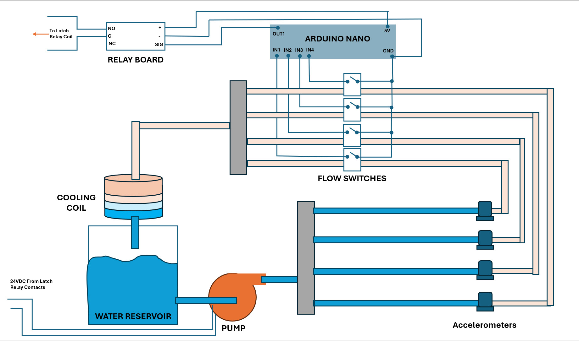
Below is a layout drawing of the water cooling system. Assuming when you mention "valve", that means solenoid valve? In my case I am not using any valves, just a pump moving water through accelerometers and flow switches reading whether there is proper flow, or not.
I have a separate circuit that turns the pump ON and OFF, using a latching relay contacts. On startup there is a timer relay that starts up the pump (5 seconds). If flow is good through flow switches a latching relay is energized and closes contacts to keep the pump working. Once a flow switch opens up for any reason, the latching relay de-energizes, contacts to pump opens and pump turns OFF. Manual reset required.
Yes, agreed. I can see some of the terms are confusing the situation.
Thank you for your example code, I will review and look at incorporating into my next version. I have something that is functional now using a7's help. The next version is to bring in that other latching circuit into a microprocessor to handle the pump startup, flow switches, water level switches, temperature and overtemp, LED indicators, alarm buzzer and possibly solenoid valves for each line to close a line based on flow for that line (vs any line with flow issues shut down the whole system).
this explanation suggests some external switch (not shown on your diagram) can also turn on the pump before the Arduino will keep it on by setting out1 HIGH. That when the Arduino recognizes that there is FLOW, the Arduino sets out1 HIGH which keeps the pumps on and allowing the external switch to be released
but it's also confusing what the Arduino can do if the external switch remains active after 5 seconds unless the external switch is an input to the Arduino and the Arduino turns on the pumps. The 5 second timer would then cause the Arduino to enter a state where is waits from the external switch to be released and pressed again to attempt to re-start the system
this code remains a mystery because it unconditionally sets out LOW. readTime will always have some value such that the condition will become true.
the timer needs a boolean (e.g. tmr) indicating that the timer is active
Yes, correct, there is a physical switch that feeds power to the pump through two contact points, one is through the timer relay contacts and a second is the latching relay contacts.The timer relay gets the pump started and shuts down after 5 seconds. If the latching relay cannot be sustained then the system shuts down and manual reset needed. If the latching relay coil circuit opens because of a safety switch opening, same thing. It's too late to change the circuit for this system, but the next one will have everything go through the Arduino microprocessor.
The switch doesn't feed the pump directly, it's flowing through the two contact points from two relays. If the latching relay energizes in say 2 seconds, then there will be flow through both contacts for another 3 seconds, then the timer relay contact opens up and only flowing through the latching relay contacts.
In the next version the pump will be controlled by an Arduino output via relay board, then write the code to detect flow through all switches in setup section, and once that happens move on the loop section to detect if any switches open for more than 2.5 seconds. I want to use the Arduino to control the initial 5 second start up time, not an external timer relay as I have on this first version.
i understand that the pump is powered thru a relay and that the relay can be energized by 2 sources.
you don't explain how the Arduino knows that the pump is being started externally and needs to start a timer and set an output to hold the relay energized
the Arduino either needs an input indicating 1) the pump is running or 2) that the relay is being energized ezternally
Please post that sketch. It will be useful as an operating specification, which along with your words and pictures will answer any questions readers might have.
Do you mean an additional microprocessor, like another Arduino board and sketch and wrangling communication betwixt?
Say more if, there really should be no need for more microprocessors. You can't be using 20 percent of the one doing the flow/relay stuff.
could be implemented with relays, but in this case it sounds like it's expected that the Arduino would "hold" it on once it start running with the 5 second timer