Advice and code check needed for Multi Strobe Project

AWOL:
When in doubt, don't try to invent syntax - it won't do what you want

digitalWrite(ledArray[0, 1, 2, 3, 4,   . . .

Nice one smart ass - Jeez why do so many of you on here feel the need to make sarcy comments like that. I didn't try to invent syntax - Cleary I just misunderstood how the syntax is used.

I was trying to refer to all of the 8 pins in the array - As it says in the comment above - so again mr.AWOL (BTW I do hope you listen to Jungle) how bout some helpful advice n not just some smart comment

I'm trying to learn as best I can :slight_smile:

Question: does the code you've posted compile?

AWOL:
Never mind the comment, what does the compiler say?

I do not know what a compiler is - Do you mean when i compile the code what does it say? If so doesn't say anything just says compile complete

What about reply #12?

AWOL:
What about reply #12?

Yeah that's fine - not sure what you think is wrong with it - I lifted that straight from the array example code?

You don't think it could be missing one of these =

?

(I'm asking these questions because I'm posting from my phone, and have no way of compiling your code)

AWOL:
You don't think it could be missing one of these =

?

Ah yeah ur right - thanks :slight_smile:

boy oh boy that was a long winded way of getting to that tho hun

So why have we been discussing code that doesn't even compile all this time?

(See reply #19)

AWOL:
So why have we been discussing code that doesn't even compile all this time?

dude it did compile? I wouldn't post code that doesn't compile haha

Maybe my software is faulty?

You don't know what a compiler is, but you wouldn't post code code that doesn't compile?

I'll leave you now. I don't have time to waste.

Aikju:

Dude... look

oops

Imgur

So I'm creating a strobe that uses multiple LED strips - And I want the speed to either be determined manually - with a potentiometer - Or automatically - with an AUX input and potentiometer.

I've created this function to be used to determine how long each delay will be:

int establishDelay() {
/*Cycle speed setting manual/automatic
  This is in order to determine whether strobe sequences cycle at a speed determined by audio
  Or at a speed set manually
 */

//Determining audio input level
int audioInput = analogRead(AUXpin);
  
//Determing potentiometer inputs

//This will = the time for each manual cycle
int manualCycle = analogRead(potPin1);

//This will = the threshold the audio input must cross to induce a cycle
int audioThreshold = analogRead(potPin2);

/*Determing if audio input will induce a single auto cycle 
  (auto cycle will take place regardless of audio input level every 2 seconds) */
  
int autoCycle = 2000;
if (audioInput > audioThreshold){
 autoCycle = 10;
}

//Determining whether delay time (time for each cycle) = manual or auto cycle

int autoActivate = digitalRead(switchPin4);

int delayTime = manualCycle;  

if (autoActivate == HIGH){
 delayTime = autoCycle;
} 
return(delayTime);
}

void loop(){

(AUXpin is connected to a AUX 3.5mm jack input and audioThreshold is set with a potentiometer)

So manual control nice and easy - Very basic. Potentiometer resistance = delay time.

But, I've realised automatic cycle won't work how I want it to. I would like it to cycle every time the audio from the music player crosses the threshold set by the potentiometer. However, with the code I've written I'm pretty sure what will happen is if the music is not over the threshold during the loop it will delay for 2 seconds and then repeat. Is there a way i can change it so it will delay until the threshold is crossed and then complete the loop and send the delay time?

I'm very new to this - only a few days experience. So please go easy on any bad coding and syntax THX

P.S. Paul S and AWOL please don't reply - I know you both love me n I appreciate ya but I'm not ready for a relationship rn Sorry </3

I think the first thing to do .... especially for a beginner such as yourself ... is to draw up a flow chart that describes very clearly the basic flow of events. And then make up some pseudocode. And then finally attempt to write the actual code.

Don’t try to write your code all at once.
Write one portion, prove it works perfectly, write then next section prove it works, repeat as needed.

Never use delay()s in your code as these freeze program execution for the delay period.

Always show us your ‘current’ compete sketch.
Use CTRL T to format the sketch.
Please use code tags.
Use the </> icon in the posting menu.

[code] Paste sketch here. [/code]

.

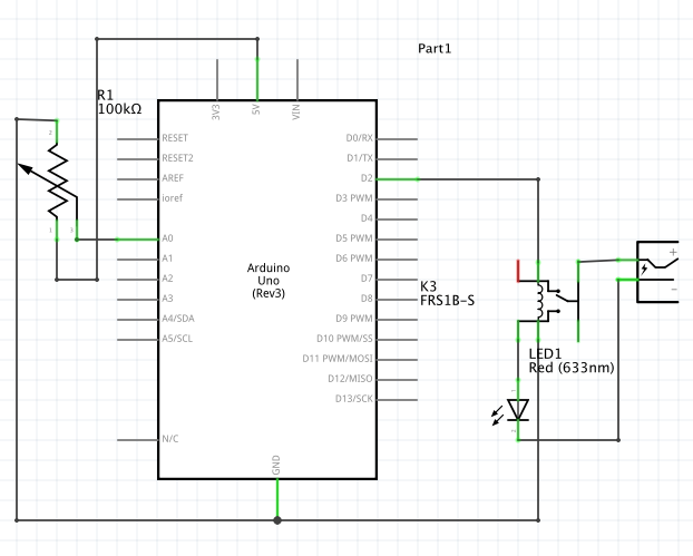
So, I've connected digital pins 2-9 each to a relay.
I want it to strobe - But, on the first cycle the relays turn on and then stay on - it's like the arduino ignores the digitalWrite syntax??? - After which they only stay LOW during the delay period after which they return HIGH

How can I use pull up/ down resistors to prevent this. I tried what I found on the web but it did resulted in the LED never going low - I assume I did it wrong then.

Here is the code:

//LED strip outputs digitalPins 0-9 

int ledArray[] = {
2, 3, 4, 5, 6, 7, 8, 9  
};

//switch pin inputs digitalPins 10-12

int switchPin1 = A1;
int switchPin2 = A2;
int switchPin3 = A3;

//potentiometers inputs analogPins A0

//manual control

int potPin1 = A0;

void setup() {
  
//setting all LED strip pins as outputs
for (int outputPin = 2; outputPin < 10; outputPin++){
  pinMode(outputPin, INPUT_PULLUP);
}

for (int outputPin = 2; outputPin < 10; outputPin++){
  pinMode(outputPin, OUTPUT);
}

//setting all switch pins as inputs

pinMode(A1, INPUT);
pinMode(A2, INPUT);
pinMode(A3, INPUT);

//setting manual control potentiometer as input

pinMode(potPin1, INPUT);

}
 
int establishDelay() {
/*Cycle speed setting manual
  This is in order to determine whether strobe sequences cycle at a speed determined by a potentiometer
 */
 
//Determing potentiometer inputs

//This will = the time for each manual cycle

int delayTime = analogRead(potPin1);


if (delayTime < 10){
  delayTime = 10; 
}

return(delayTime);
}

void loop() {

//Sequence 1>3>2>4>3>5>4>6>5>7>6>8>7>8>6>7>5>6>4>5>3>4>2>3>1>2

digitalWrite(ledArray[0], HIGH);
delay( establishDelay() );
digitalWrite(ledArray[0], LOW);
delay( establishDelay() );
digitalWrite(ledArray[2], HIGH);
delay( establishDelay() );
digitalWrite(ledArray[2], LOW);
delay( establishDelay() );
digitalWrite(ledArray[1], HIGH);
delay( establishDelay() );
digitalWrite(ledArray[1], LOW);
delay( establishDelay() );
digitalWrite(ledArray[3], HIGH);
delay( establishDelay() );
digitalWrite(ledArray[3], LOW);
delay( establishDelay() );
digitalWrite(ledArray[2], HIGH);
delay( establishDelay() );
digitalWrite(ledArray[2], LOW);
delay( establishDelay() );
digitalWrite(ledArray[4], HIGH);
delay( establishDelay() );
digitalWrite(ledArray[4], LOW);
delay( establishDelay() );
digitalWrite(ledArray[3], HIGH);
delay( establishDelay() );
digitalWrite(ledArray[3], LOW);
delay( establishDelay() );
digitalWrite(ledArray[5], HIGH);
delay( establishDelay() );
digitalWrite(ledArray[5], LOW);
delay( establishDelay() );
digitalWrite(ledArray[4], HIGH);
delay( establishDelay() );
digitalWrite(ledArray[4], LOW);
delay( establishDelay() );
digitalWrite(ledArray[6], HIGH);
delay( establishDelay() );
digitalWrite(ledArray[6], LOW);
delay( establishDelay() );
digitalWrite(ledArray[5], HIGH);
delay( establishDelay() );
digitalWrite(ledArray[5], LOW);
delay( establishDelay() );
digitalWrite(ledArray[7], HIGH);
delay( establishDelay() );
digitalWrite(ledArray[7], LOW);
delay( establishDelay() );
digitalWrite(ledArray[6], HIGH);
delay( establishDelay() );
digitalWrite(ledArray[6], LOW);
delay( establishDelay() );
digitalWrite(ledArray[7], HIGH);
delay( establishDelay() );
digitalWrite(ledArray[7], LOW);
delay( establishDelay() );
digitalWrite(ledArray[5], HIGH);
delay( establishDelay() );
digitalWrite(ledArray[5], LOW);
delay( establishDelay() );
digitalWrite(ledArray[6], HIGH);
delay( establishDelay() );
digitalWrite(ledArray[6], LOW);
delay( establishDelay() );
digitalWrite(ledArray[4], HIGH);
delay( establishDelay() );
digitalWrite(ledArray[4], LOW);
delay( establishDelay() );
digitalWrite(ledArray[5], HIGH);
delay( establishDelay() );
digitalWrite(ledArray[5], LOW);
delay( establishDelay() );
digitalWrite(ledArray[3], HIGH);
delay( establishDelay() );
digitalWrite(ledArray[3], LOW);
delay( establishDelay() );
digitalWrite(ledArray[4], HIGH);
delay( establishDelay() );
digitalWrite(ledArray[4], LOW);
delay( establishDelay() );
digitalWrite(ledArray[2], HIGH);
delay( establishDelay() );
digitalWrite(ledArray[2], LOW);
delay( establishDelay() );
digitalWrite(ledArray[3], HIGH);
delay( establishDelay() );
digitalWrite(ledArray[3], LOW);
delay( establishDelay() );
digitalWrite(ledArray[1], HIGH);
delay( establishDelay() );
digitalWrite(ledArray[1], LOW);
delay( establishDelay() );
digitalWrite(ledArray[2], HIGH);
delay( establishDelay() );
digitalWrite(ledArray[2], LOW);
delay( establishDelay() );
digitalWrite(ledArray[0], HIGH);
delay( establishDelay() );
digitalWrite(ledArray[0], LOW);
delay(establishDelay());
digitalWrite(ledArray[1], HIGH);
delay( establishDelay() );
digitalWrite(ledArray[1], LOW);
delay( establishDelay() );                 
}

Show us your schematic.

aarg:
Show us your schematic.

I do not know why this has fed back into one of my old threads?

Aikju:

Well the relay connection really looks goofy. What is the little red line that goes nowhere? Where is the flyback diode on the coil to suppress back EMF? Where are the other seven relays?

Aikju:
I do not know why this has fed back into one of my old threads?

Because it's about the same project, perhaps?