I am using an Arduino to do some measuring of light intensity for me, this is for a structured light application so these measurements will need to be done upon reception of a trigger pulse from an external device.
My external device has a 3.3V trigger that upon analysing with Analog Read in a test program appears to be outputting sensible data.
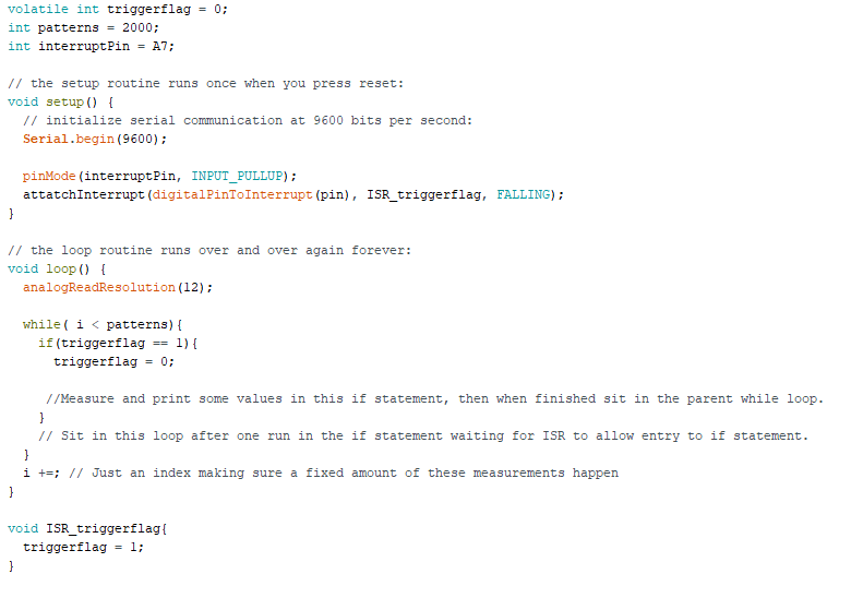
My understanding of a good way to do this is to avoid polling methods and use interrupts, I have attatched a picture of a general way I think that these methods should be implemented but would appreciate some advice on some places I may be going wrong as when I have practically tried to set this up I get some misbehaving going on.
Most importantly at times when running through a sequence of measurements at high frequency occasionaly what should have been a single trigger pulse will cause two measurements. This is a disaster for my application as the measurements taken form a strictly ordered basis, so any extra measurements displace all subsequent measurements.
I have also attatched the form of the trigger pulse (which can be inverted to use either rising or falling with it) so that my problem is a little clearer.
My main question is whether there is anything obvious in my code conceptually that is going to be a difficulty for interrupts? Or if the problem is more likely to be with the electron signal for the trigger that needs some cleaning up?
Also is it even a good idea to start with sticking with this interrupt method or should I be considering using polling somehow?
Or if the problem is more likely to be with the electron signal for the trigger that needs some cleaning up?
it probably wont hurt to add a small capacitor fed via a resistor (to limit current) if you want to remove double triggers. As for the code please post it within </> code-tags.
Thank you for the advice on the electronics I will definitely try and implement this change tomorrow
As for the general code if this works
volatile int triggerflag = 0;
int patterns = 2000;
int interruptPin = A7;

int readpin = A0;

int n = 10;
int j = 0;
int i = 0;
int val = 0;


// the setup routine runs once when you press reset:
void setup() {
  // initialize serial communication at 9600 bits per second:
  Serial.begin(9600);
  pinMode(interruptPin, INPUT_PULLUP);
  //attachInterrupt(digitalPinToInterrupt(interruptPin),ISR_triggerFlag, FALLING);
}

// the loop routine runs over and over again forever:
void loop() {

  analogReadResolution(12);

  while(i < patterns){
    if(triggerflag ==1){
      triggerflag = 0;

      //Function of code is to read some analog values from a pin and print them to a serial monitor
      while(j < n){
        delayMicroseconds(1);
        val = analogRead(readpin);
        delayMicroseconds(1);
        Serial.println(val);
        j += 1;
      }
       //Code hopefully in this while loop unable to enter the if statement until a trigger is sent
    }

    //index changes etc goes here, plus comma seperates variables
    Serial.println("'");
    i += 1;
  }


}

void ISR_triggerFlag{
  triggerflag = 1;
}
This is code I just wrote as I am no longer with the machine that I was experimenting on, however it has all the same elements. I also figured to add more details about the measuring process incase there was any problem with interrupts interacting with any of my other functions like delays or something.
Also in regards to scale this problem first starts appearing when the trigger is outputted at around 12Hz, however in the future we are hoping to push the pattern rate far beyond that. (In that range of 1440 Hz)
The board is an Arduino Due, which according to the documentation should be usable with interrupts on all digital pins. Currently the problem we are having remains on all pins we have tried. (Digital 3 and 4 + A7 so we could monitor the analog output of the trigger to get a better idea what was happening).