ADXL335 for Nasa Crawler

Here is my project: 3D printing Motorized Nasa Crawler

I am printing the whole structure and I would like to motorize the up/down of the platform with four DC 6V motors like these

I need the platform to always stay horizontal, I'm going to use an ADXL335 with an arduino to do this

Has anyone ever made such a program for my project?

first of all:
this is a really great engineering project with which you will learn a lot.

realising this vehicle is a very interesting project for sure
and watching it in action driving over uneven ground keeping the platform flat-level will be very cool.

for your project? very sure NO!

I guess you mean has anyone ever written a program that works with the ADXL335 3-axis acceleration analog output sensor that measures the direction of the gravity vector ?

Has anyone ever written a program that is leveling a platform with DC motors?

To make an analogon:
You are asking this way

I have this set lego-tec parts
image

has anyone ever build a lego-model of this bike with this set of parts?

As you can easily estimate with the lego-tec parts shown in the picture it is very unlikely to build a model of this crazy bike.

programming is like building things with lego.

There are small parts with all kinds of shapes with which you can build almost anything
up to a real size bugatti veyron by combining different parts
image

You seem to greatly underestimate the effort for writing this program.
This is not done in 3 hours with 300 lines of code

You should do some calculations first:
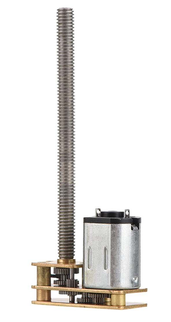
what is the maximum rpm of these geared DC-motors with thread

what is the maximum speed how fast you can move the platform up-down with the given
gear-ratio from motor-shaft to the linear motion of the platform

how fast do you want to drive the crawler over ground ?
how big shall the slope be that the crawler shall be climbing up/down with one "driving-leg"
and for keeping the platform flat-level must be able to move the "driving-leg" up/down?

If you are willing to learn and showing you are putting constantly and continiously own effort into this project it will be very intriguing for others to give support to this project.

Finding code for electronic components that is useful
starts with googling with the keywords

"github arduino YOUR_KEYWORD_OF_INTEREST"

In your case
github arduino ADXL335
https://www.google.com/search?q=github+arduino+ADXL335

which will guide you to libraries that makes reading in the signal of the ADXL335 much easier than programming from scratch.

best regards Stefan

My apologies for the bad wording!

I wanted to know if anyone had already made or seen a project that uses this kind of component to keep a platform horizontal with this type of actuator...

Raising and lowering objects is a typical use for a linear actuator. You will need a traveling nut on the lead screw.

To use the ADXL335 as a tilt sensor for leveling a platform, the basic idea is described here: How_to_Use_a_Three-Axis_Accelerometer_for_Tilt_Sensing-DFRobot

It seems like it gets really complex when you have four corners to adjust. What happens when the system is traveling over uneven terrain? Which corner do you use as reference point for leveling or do you use the center as reference which seems like it would reduce the sensitivity greatly? etc.

The lead screw method with DC motor and no feed back would add to the complexity.

I imagine such a beast would have to travel very, very slowly, and be quite limited in the obstacles and slopes it could negotiate.

A SciFi story describes people living on a structure which continuously traveled on rails around the equator of the planet Mercury, remaining on the dawn line.

Thank you for all these answers, my goal was to control the angle of the platform during raising/lowering , the Crawler will always roll on flat.
I think I'm going to make a control system for each motors with a digital level display thanks to the ADXL335, it will be easier

Even easier if you use stepper driven actuators instead of brushed DC motors. Since a properly designed stepper system doesn't skip steps, you know the extension of the actuator arm.

May I make a suggestion (I am not a pro but might be able to help)? I use the MPU6050 and are happy with their performance. May i suggest you mount one or more (as backups, so each can compare to each other in real time and "self diagnose" if one or more is significantly out of kilter).

The output of the MPU6050 can easily translate (via a BRUSHED not BRUSHLESS Your motor in the pic is clearly a hobbly BRUSHED motor) to current to the correct motor to right the system. Of course you will eventually run out of "thread" on the bar if that is all it does so the opposing sides must run in reverse etc.

But it should be easy to do. No need for PID controller (IMHO) or the like. Since the adjustments are in real time the MPU6050 provides a constant feed back to the microcontroller and thus the current from the BRUSHED controller.

May I also suggest using a ready made linear actuator you can pick up cheep on eBay for each wheel assembly. In ebay search for "2"-18" Inch Stroke Linear Actuator 1500N/330lbs Pound Max Lift 12V Volt DC Motor" they start at 7 dollars!

Keep in mind I am assuming this beast will not be faster than 1/2 human walking speed. Otherwise you might want to consider several different kinds of suspension systems (depending on terrain type, etc).

I remember that book!! Darn I can't remember the title, but I do remember the story , always in the night side of the planet for obvious reasons.

assuming they are working correctly / calibrated and such. But the 3-axis sensor can verify and even auto-compensate (via microcontroller) / send a warning of pending failure (AE-35 any one?). That would add some cool functionality for not many lines of code.

That will simplify things. You might consider at least a once per revolution encoder to keep track of the vertical motion of each corner. You may want to include some limit switches to indicate when the platform is fully retracted.

I think the author was Alastair Reynolds, one of the more imaginative writers.

I would think using opposites simultaneouly might be best? That might (might!) eliminate the issue: for example: machine is on a 10% grade to the right. Then the two right arms lower the right a bit as the two left arms raise a bit. Thus you never "run out of" thread or linear actuator length. The machine would always be "floating" around the mid point (length wise) of the actuator arms (or thread length from the photo OP posted).

I looked at his book list on line. None ring a bell. Crap... now this is going to drive me bonkers till I go through all my boxes of old books in the shed! LOL

If you use the lead screw pictured which has an M4 screw your motion will be pretty slow so you’ll have plenty of time to coordinate the motion of the 4 corners. You’re limiting the terrain to level ground will help to simplify the problem.
If you use a lead screw with a 30RPM motor your vertical travel will be on the order of 20mm per minute so I don’t see a need to control the motor speed. Two speeds, slow and stopped. :grinning:
What is the scale of your model?

I dug around and am now pretty sure it was Kim Stanley Robinson's "2312". 2312: Robinson, Kim Stanley: 9780316526982: Amazon.com: Books

The city Terminator moves on tracks heated by the sun. Must be nice to have the unlimited funds, materials and fail-safe technology to make things like that.

And the incentive!

why the heck does that ring a bell? I read the synopsis on the book on line... that might be it but I thought I stopped reading Sci Fi before 2012... what ever the heck, I must be getting old...

There are similar stories, as described in this thread: Short-story about moving "cathedral" cities on a Mercury-like planet - Science Fiction & Fantasy Stack Exchange