Hi everyone, I am trying to use ADXL345 and I want to measure steps. I found Analog Dialogue about it. It says, signal needs to be smoother so he used this.
So what I want to ask, For example, if I add 4 values and then average them, is it a filter?
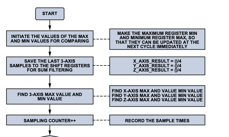
I'm reading code instructions for detect steps. It says,
INITIATE THE VALUES OF THE MAX AND MIN VALUES FOR COMPARING
MAKE THE MAXIMUM REGISTER MIN AND MINIMUM REGISTER MAX, SO THAT THEY CAN BE UPDATED AT THE NEXT CYCLE IMMEDIATELY
I don't understand this. Why should I make max to min and min to max ?
In the arduino forum, I found something like this
 if(sampling == 0)
  {
    maxave = ave;
    minave = ave;
  }
I don't understand how this work How can i reflect this approach in code ?
the typical algorithm to find the min and max of a future flow of data is to initialise the min and max to out of range values so that they will be overridden when you get the first data in the flow. In order to make sure they are overriden, you need to pick a super low value for the max and a super high value for the min.
example:
int maxValue = -20000;   // impossible value as the range is 0 to 1024
int minValue = 20000;    // impossible value as the range is 0 to 1024

for (int i = 0; i < 100; i++) {
  int v = analogRead(A0); // will be between 0 and 1024
  if (v > maxValue) maxValue = v;
  if (v < minValue) minValue = v;
}

Serial.print("Min = ");  Serial.println(minValue);
Serial.print("Max = ");  Serial.println(maxValue);
if you are looking for the min and max in an array (not a flow of unknown value) usually you initialise the min and max with the first entry of the array and then let those evolve as you go through the array. that might be the second option you presented
jackson has presumably addressed your min/max issue
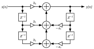
no. the diagram below is accurate and more general
"x" represents input samples and "y" output.
triangular boxes represents a multipliers.
boxes with "z" represent a delay.
the current input is multiplied by b0, the previous input by b1 and the sample before that by b2. they are all added together and are a component of the output, "y".
but the output, "y", is also feed back. the previous output is multiplied by -a1 and the one prior to that -a2 which are also added to the output, "y"
an FIR filter without the feedback elements is often used
yes, he's just averaging the last four values. could shift each value thru some sort of pipe, sum all the values and average them, or use an array and replace the oldest value, sum and average.
Yep, nor would I. Just simple averaging which programmers commonly refer to as smoothing.
Averaging is not what I would call filtering, unless one just wants to call it time-differential averaging of the unbiased kind. Smoothing does "filter" spikes from the results, so in a crude way it is ceiling/floor filtering.