Air Flow meter

Hi Guys,

Need some advise on reading flow from SMC Pneumatic's airflow meter.
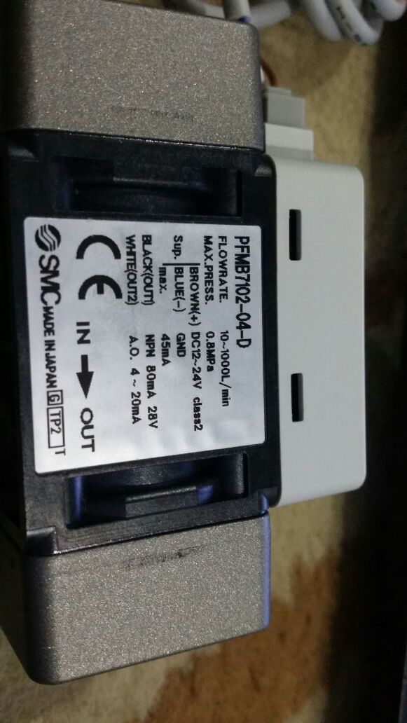
Output from sensor: 4mA-20mA.
Been trying to figure out how do get the flow from this sensor out to be read by my Arduino Uno. Does anyone have any idea? I need to use this flowmeter to measure the amount of air i consume daily... so i can get some info of how much of air i'm wasting at my tools at work...

Please help me out...

I've the picture of the flowmeter attached with this...

got this code from DIY hack...
Still not able to read anything from sensor....

/*
Liquid flow rate sensor -DIYhacking.com Arvind Sanjeev

Measure the liquid/water flow rate using this code.
Connect Vcc and Gnd of sensor to arduino, and the
signal line to arduino digital pin 2.

*/

byte statusLed = 13;

byte sensorInterrupt = 0; // 0 = digital pin 2
byte sensorPin = 2;

// The hall-effect flow sensor outputs approximately 4.5 pulses per second per
// litre/minute of flow.
float calibrationFactor = 4.5;

volatile byte pulseCount;

float flowRate;
unsigned int flowMilliLitres;
unsigned long totalMilliLitres;

unsigned long oldTime;

void setup()
{

// Initialize a serial connection for reporting values to the host
Serial.begin(38400);

// Set up the status LED line as an output
pinMode(statusLed, OUTPUT);
digitalWrite(statusLed, HIGH); // We have an active-low LED attached

pinMode(sensorPin, INPUT);
digitalWrite(sensorPin, HIGH);

pulseCount = 0;
flowRate = 0.0;
flowMilliLitres = 0;
totalMilliLitres = 0;
oldTime = 0;

// The Hall-effect sensor is connected to pin 2 which uses interrupt 0.
// Configured to trigger on a FALLING state change (transition from HIGH
// state to LOW state)
attachInterrupt(sensorInterrupt, pulseCounter, FALLING);
}

/**

  • Main program loop
    */
    void loop()
    {

if((millis() - oldTime) > 1000) // Only process counters once per second
{
// Disable the interrupt while calculating flow rate and sending the value to
// the host
detachInterrupt(sensorInterrupt);

// Because this loop may not complete in exactly 1 second intervals we calculate
// the number of milliseconds that have passed since the last execution and use
// that to scale the output. We also apply the calibrationFactor to scale the output
// based on the number of pulses per second per units of measure (litres/minute in
// this case) coming from the sensor.
flowRate = ((1000.0 / (millis() - oldTime)) * pulseCount) / calibrationFactor;

// Note the time this processing pass was executed. Note that because we've
// disabled interrupts the millis() function won't actually be incrementing right
// at this point, but it will still return the value it was set to just before
// interrupts went away.
oldTime = millis();

// Divide the flow rate in litres/minute by 60 to determine how many litres have
// passed through the sensor in this 1 second interval, then multiply by 1000 to
// convert to millilitres.
flowMilliLitres = (flowRate / 60) * 1000;

// Add the millilitres passed in this second to the cumulative total
totalMilliLitres += flowMilliLitres;

unsigned int frac;

// Print the flow rate for this second in litres / minute
Serial.print("Flow rate: ");
Serial.print(int(flowRate)); // Print the integer part of the variable
Serial.print("."); // Print the decimal point
// Determine the fractional part. The 10 multiplier gives us 1 decimal place.
frac = (flowRate - int(flowRate)) * 10;
Serial.print(frac, DEC) ; // Print the fractional part of the variable
Serial.print("L/min");
// Print the number of litres flowed in this second
Serial.print(" Current Liquid Flowing: "); // Output separator
Serial.print(flowMilliLitres);
Serial.print("mL/Sec");

// Print the cumulative total of litres flowed since starting
Serial.print(" Output Liquid Quantity: "); // Output separator
Serial.print(totalMilliLitres);
Serial.println("mL");

// Reset the pulse counter so we can start incrementing again
pulseCount = 0;

// Enable the interrupt again now that we've finished sending output
attachInterrupt(sensorInterrupt, pulseCounter, FALLING);
}
}

/*
Insterrupt Service Routine
*/
void pulseCounter()
{
// Increment the pulse counter
pulseCount++;
}

still struggling...

http://forum.arduino.cc/index.php/topic,148850.0.html

start with #7

the device outputs 4-20ma

i was thinking you would have an analog input for that ?

you have the input on pin 2 and have that as a byte.

assuming you have a resistor for the input, you loose 20% of the scale.
so using byte reduces overall resolution

I think you have the wrong program ?.

Hi,
The program you have is for a flow meter that has pulse output, yours has analog output.
You just need to put a 250 Ohm resistor across the current output of the flowmeter, output 2 and negative.
And then connect the gnd of the arduino up to the negative terminal of the flowmeter output.
Connect the analog input of the arduino to the output 2 terminal of the flowmeter.

The resistor will convert the current into a voltage output of, 1 to 5V which is suitable for the arduino.
The software you have will not work, so you will need new software that can calculate the offset and scale the AtoD conversion to the units you require.

Tom.... :slight_smile:
250 Ohms can be made up using 4 x 1K resistors in parallel.

dave-in-nj:
the device outputs 4-20ma

i was thinking you would have an analog input for that ?

you have the input on pin 2 and have that as a byte.

assuming you have a resistor for the input, you loose 20% of the scale.
so using byte reduces overall resolution

I think you have the wrong program ?.

Hi Dave any suggestions? I'm looking around for a good solution.
Have not gone into using arduino's analog input. Do you have any idea how to get an analog input to be read by my arduino uno?

Thank you.

TomGeorge:
Hi,
The program you have is for a flow meter that has pulse output, yours has analog output.
You just need to put a 250 Ohm resistor across the current output of the flowmeter, output 2 and negative.
And then connect the gnd of the arduino up to the negative terminal of the flowmeter output.
Connect the analog input of the arduino to the output 2 terminal of the flowmeter.

The resistor will convert the current into a voltage output of, 1 to 5V which is suitable for the arduino.
The software you have will not work, so you will need new software that can calculate the offset and scale the AtoD conversion to the units you require.

Tom.... :slight_smile:
250 Ohms can be made up using 4 x 1K resistors in parallel.

Hi Tom,

I tried putting the resister across the input to make it into a pulse input. still i dont know where i went wrong.
Been away with work so had no time to go back to my board to do any hook ups for now.

Thank you.

A year ago we bought a nitrogen generation system. Seller could never get it to produce the quality and volume of N2 they sold us.

They put a similar device in the output line to measure the N2 flow. It was connected into the system control box for power. The meter itself cannot supply the 24 volts it only acts as a variable resistor to control the current in the loop. You need to supply the power for the device you have.

Paul

Paul_KD7HB:
A year ago we bought a nitrogen generation system. Seller could never get it to produce the quality and volume of N2 they sold us.

They put a similar device in the output line to measure the N2 flow. It was connected into the system control box for power. The meter itself cannot supply the 24 volts it only acts as a variable resistor to control the current in the loop. You need to supply the power for the device you have.

Paul

Hi Paul,

Yes i have an external power to run the flow meter. Just that i'm unable to interpret the output which is a 4mA to 20mA analog output.

Thank you.

You should be able to use the code you've provided if you use the NPN output (black wire) of the sensor. To the right is an interface I propose (untested):

Operation Manual

dlloyd:
You should be able to use the code you've provided if you use the NPN output (black wire) of the sensor. To the right is an interface I propose (untested):

Operation Manual

Hi dlloyd,

thank you for your idea. Shall try it out tonight and check if the schematic works... thank you very much for the info and help.

Hi dyllod,

sorry my laptop crashed while i was testing the circuit.
i found the circuit you suggested did not work.
there was no reading from the Serial monitor output.
Anyways for you to verify the connections again, as my analog output is the white cable - 420mA

thanks.

http://www.smcworld.com/upfiles/manual/e/PF-OMP0002.pdf

look at your device,
then determine what part you have
then look at the output wiring available.

of course the proposed wiring will not work. you have an analog output device.

you will need to connect it to an analog input pin.

put power to the brown wire, 12DC
put a 500 ohm or some such 470, 520, etc from white to ground.
put white onto your Analog inptu pin.
tie the sensor ground to your arduino ground.

go to post #2, read, follow the link
go to post #1, highlight the text that is the program and then follow the instructions on item #7 and put your code in code tags.

you could just erase it as it does not apply to this device.

this is a bit sloppy. sorry, windoz locked out my network card and I am redused to running a unbuntu box and cannot do a proper sketch. (seems right click does not have any effect in the paint program on unbuntu, sigh)

[color=#cc6600]int[/color] analogPin = 3;     [color=#7e7e7e][i]// analog input on pin 3[/i][/color]
[ltr]                      [color=#7e7e7e][i]// outside leads to ground and +5V[/i][/color]
[color=#cc6600]int[/color] val = 0;           [color=#7e7e7e][i]// variable to store the value read[/i][/color]

[color=#cc6600]void[/color] [color=#cc6600][b]setup[/b][/color]()
{
 [color=#cc6600]Serial[/color].[color=#cc6600]begin[/color](9600);      [color=#7e7e7e][i]//  setup serial  you have to open the serial window in your arduino [/i][i]program[/i][/color]
}

[color=#cc6600]void[/color] [color=#cc6600][b]loop[/b][/color]()
{
 val = [color=#cc6600]analogRead[/color](analogPin);    [color=#7e7e7e][i]// read the input pin[/i][/color]
 [color=#cc6600]Serial[/color].[color=#cc6600]println[/color](val);             [color=#7e7e7e][i]// debug value[/i][/color]
}[/ltr]

viswa_devan:
Hi dyllod,

sorry my laptop crashed while i was testing the circuit.
i found the circuit you suggested did not work.
there was no reading from the Serial monitor output.
Anyways for you to verify the connections again, as my analog output is the white cable - 420mA

thanks.

what threshold did you set the device to trip the switch ?
the black wire is the on/off alarm that signals either too much flow or too little flow. it should have tripped between full flow and no flow.
the white wire will be the one to use for analog. whole different wiring needed for that.

there was no reading from the Serial monitor output.

I changed your code (below) to use 115200 baud for the serial monitor because 38400 has problems with various versions of the Arduino IDE.

i found the circuit you suggested did not work.

The the interface should work, but its untested. It uses the digital output wire (black). The analog wire (white) is not needed.

Did you program OUT1 (black wire) for accumulated pulse output mode?
You can even change its polarity ... I believe either way should work.
See page 28+ in the manual.

Your test code (tested on Arduino Due using push button pulses, works OK):

/*
Liquid flow rate sensor -DIYhacking.com Arvind Sanjeev

Measure the liquid/water flow rate using this code.
Connect Vcc and Gnd of sensor to arduino, and the
signal line to arduino digital pin 2.

 */

byte statusLed    = 13;

byte sensorInterrupt = 0;  // 0 = digital pin 2
byte sensorPin       = 2;

// The hall-effect flow sensor outputs approximately 4.5 pulses per second per
// litre/minute of flow.
float calibrationFactor = 4.5;

volatile byte pulseCount;

float flowRate;
unsigned int flowMilliLitres;
unsigned long totalMilliLitres;

unsigned long oldTime;

void setup()
{

  // Initialize a serial connection for reporting values to the host
  Serial.begin(115200);

  // Set up the status LED line as an output
  pinMode(statusLed, OUTPUT);
  digitalWrite(statusLed, HIGH);  // We have an active-low LED attached

  pinMode(sensorPin, INPUT_PULLUP);
  digitalWrite(sensorPin, HIGH);

  pulseCount        = 0;
  flowRate          = 0.0;
  flowMilliLitres   = 0;
  totalMilliLitres  = 0;
  oldTime           = 0;

  // The Hall-effect sensor is connected to pin 2 which uses interrupt 0.
  // Configured to trigger on a FALLING state change (transition from HIGH
  // state to LOW state)
  attachInterrupt(sensorInterrupt, pulseCounter, FALLING);
}

/**
 * Main program loop
 */
void loop()
{

  if ((millis() - oldTime) > 1000)   // Only process counters once per second
  {
    // Disable the interrupt while calculating flow rate and sending the value to
    // the host
    detachInterrupt(sensorInterrupt);

    // Because this loop may not complete in exactly 1 second intervals we calculate
    // the number of milliseconds that have passed since the last execution and use
    // that to scale the output. We also apply the calibrationFactor to scale the output
    // based on the number of pulses per second per units of measure (litres/minute in
    // this case) coming from the sensor.
    flowRate = ((1000.0 / (millis() - oldTime)) * pulseCount) / calibrationFactor;

    // Note the time this processing pass was executed. Note that because we've
    // disabled interrupts the millis() function won't actually be incrementing right
    // at this point, but it will still return the value it was set to just before
    // interrupts went away.
    oldTime = millis();

    // Divide the flow rate in litres/minute by 60 to determine how many litres have
    // passed through the sensor in this 1 second interval, then multiply by 1000 to
    // convert to millilitres.
    flowMilliLitres = (flowRate / 60) * 1000;

    // Add the millilitres passed in this second to the cumulative total
    totalMilliLitres += flowMilliLitres;

    unsigned int frac;

    // Print the flow rate for this second in litres / minute
    Serial.print("Flow rate: ");
    Serial.print(int(flowRate));  // Print the integer part of the variable
    Serial.print(".");             // Print the decimal point
    // Determine the fractional part. The 10 multiplier gives us 1 decimal place.
    frac = (flowRate - int(flowRate)) * 10;
    Serial.print(frac, DEC) ;      // Print the fractional part of the variable
    Serial.print("L/min");
    // Print the number of litres flowed in this second
    Serial.print("  Current Liquid Flowing: ");             // Output separator
    Serial.print(flowMilliLitres);
    Serial.print("mL/Sec");

    // Print the cumulative total of litres flowed since starting
    Serial.print("  Output Liquid Quantity: ");             // Output separator
    Serial.print(totalMilliLitres);
    Serial.println("mL");

    // Reset the pulse counter so we can start incrementing again
    pulseCount = 0;

    // Enable the interrupt again now that we've finished sending output
    attachInterrupt(sensorInterrupt, pulseCounter, FALLING);
  }
}

/*
Insterrupt Service Routine
 */
void pulseCounter()
{
  // Increment the pulse counter
  pulseCount++;
}