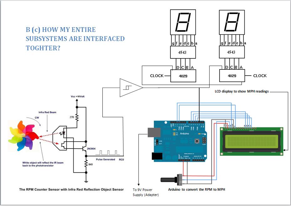
I am doing a project for my electronics Alevel. The aim is to develop a wind speed detector by using a Arduino UNO, Reflective Infra-red sensor and a LCD (see the attached JPG for interfacing diagram).
Current Logic:
The pulses coming from the Reflective Infra-red sensor increments a variable 'rpmcount' at every rising edge. Currently, I divide this by the number of wind blades. Below is my sketch so far.
Current Result:
For some unknown reason, it keeps reading RPM as 2.35mph even though I haven’t connected the output of the reflective sensor to arduino (bug?).
(Sorry AWOL I understand what you were trying to say at that time now. I have corrected myself and made it more clearer for people in future. Thanks for your advice, it really did help to get this project working 5 years ago. I was quite the newbie. )
#include

// initialize the library with the numbers of the interface pins
LiquidCrystal lcd(7, 8, 9, 10, 11, 12);

volatile byte rpmcount;

unsigned int rpm;
float speed;

unsigned long timeold;

void setup()
{
lcd.begin(16, 2); // Set up the LCD’s number of columns and rows:
lcd.setCursor(0, 0); // Sets the posiion of the cursor
lcd.print(“Hello World”); // Print a message to the LCD.
lcd.setCursor(0, 1); // Sets the posiion of the cursor
lcd.print(“WSD2011?); // Print a message to the LCD.
delay(4000); // Delay for opening message
lcd.begin(16, 2); // Clear Screen
attachInterrupt(0, rpm_fun, RISING); // input pulse, pin 2
rpmcount = 0;
rpm = 0;
timeold = 0;
}

void loop()
{
if (rpmcount >= 30) {
//Update RPM every 30 counts, increase this for better RPM resolution,
//decrease for faster update
// calculate the revolutions per minute
rpm = ((30*1000/(millis() – timeold))*rpmcount)/6;
timeold = millis();
rpmcount = 0;
// WHEELCIRC = 2 * PI * radius (in meters)
// speed = (rpm * WHEELCIRC * “minutes per hour”) / “meters per miles”

// simplify the equation to reduce the number of floating point operations
// speed = 60* rpm* WHEELCIRC* 1/ 1609.344 —- In mph

speed = (60* rpm* 0.251)/1609.344;

lcd.setCursor(0, 0); // Sets the posiion of the cursor
lcd.print(“RPM:”); // Print a rpm lable to the LCD.
lcd.setCursor(6, 0); // Sets the posiion of the cursor
lcd.print(rpm,DEC); // Print rpm value
lcd.setCursor(0, 1); // Sets the posiion of the cursor
lcd.print(“Speed:”); // Print a speed lable to the LCD.
lcd.setCursor(7, 1); // Sets the posiion of the cursor
lcd.print(speed,2); // Print speed value
lcd.println(” mph”); // Speed unit
}
}

void rpm_fun()
{
rpmcount++;
//Each rotation, this interrupt function is run twice
}
even though i haven’t connected the output of the reflective opto switch to the digital pin 2, but jumper wire has to be in order to show this on digital pin 2.
sentence means, please?
if (rpmcount >= 30) {
//Update RPM every 20 counts
?
(in case anyone is wondering, an A-level is an examination usually taken at age 18, just prior to university)
A jumper wire connected to Digital Input pin 2 on arduino (the other end not connected to anywhere.).
If nothing is connected then the arduino only displays the 2 messages from the sketch then stops. (I had no idea about how my program even worked at this point. lol (My future self is laughing at this idiot! In my defence, this was my first program ever and now here I am a fully qualified Software Engineer.))
do you mean the wire is acting as a antenna? (picking up readings from air (noise))
But I tried connecting the other end to a breadboard but the reading still stay the same. (any ideas?)
If an input pin is not connected to anything, it is said to be floating.
This means that, if you read it, you can't be sure what it will return - maybe HIGH, maybe LOW.
If the pin is an interrupt, you may get spurious interrupts.
Connecting the pin to either the supply rail or the ground via a resistor means that if you disconnect the pin, you can be sure it will consistently read high (supply) or low (ground).
The AVR provides pullup (connected to supply) internally, or you can use external resistors for pullup or pulldown.
The internal pullups are enabled by performing a "digitalWrite (myPin, HIGH);" on a pin configured as an input.
have u seen the picture that i have attached....i connected all the wires accordingly....can u plz refer with this
I don't have any pull-ups or pull-down on pin 2. Only had a interrupt at every rising edge. "attachInterrupt(0, rpm_fun, RISING); // input pulse, pin 2"
Can you give me a snippet of enabling the pull-ups or the pull-down on digital pin 2? (which you already have, kindof!). do I have to add this to the void setup ()