I'm trying to make an ammeter with arduino. The goal here is to achieve a few percent accuracy when measuring several hundred milliamps of current through a circuit, say a battery and a light bulb.
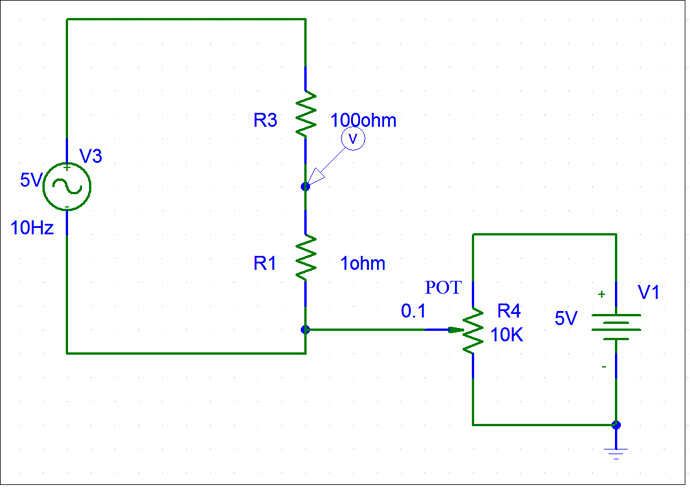
Here is my diagram:
Basically the left circuit's current is to be measured via the voltage across a 1 Ohm resistor in series with the 100 ohm light bulb. I gave it an ac source so I can explore negative currents. The right circuit is a voltage divider on a 10K ohm pot. I get a 500mV on the wiper and add that 500mV to the voltage of the 1 ohm resistor so the analog pin (V symbol) will always stay positive in voltage for (+/-) 500mA range. I will use internal voltage reference of 1.1V.
Any problems with this design? I want both positive and negative currents within a small range. I think my setup with 500mV to shift the measured voltage, I can explore around (+/-) 500mA range since 1 ohm * (+/-)500mA+500mV has range of 0-1V.
