Is it somehow possible to put 5V on the Analog ports or somehow turn on or off a 5V line (if possible without further parts?)?
Not sure what you are asking. However if your question is can an Arduino analog input pin be operated like a digital output pin, then the answer is yes. If you use pin number 14 in your digital pin commands then it will operate on analog pin #0 as a digital pin.
Does that help?
Lefty
You can use the analog in pins as digital pins by using digital write on the analog pin's number (0-5) + 14 (so analog pin 3 is actually digital pin 17). So yes, just set the pin you need to high and you get 5v @ 40ma
hmm.. thats exactly what i did (digitalWrite(14,HIGH)).. yet the outcome is different from using the 5V pin...
I guess it has to do with only having 40ma...
is there a way to have more? (DOES the 5V pin have more?)
How would i have to use a transistor to toggle a 5V line on or off?
Digital pins all output at 40 ma, but the 5v pin goes to 200ma from what I remember... I'm not completely sure about that though, but you can be sure that it is certainly more than 40ma
You are not taking anything out of the 5V pin of the chip, so it is a none question.
Exactly what are you trying to do with the pin? Do you need it to be an analogue input one moment and then under program control switch it to a high current source? If so you could use an analogue switch but even thoe are limited as to current.
in the end i would like to have several 5V lines that i can turn on or off. obviously the Analog lines arent powerful enough, so i am stuck with the 5V line and i will have to womehow get 4 lines from it which are switchable (to eiether 5V or Off).
What about an external power source, a 5v regulator --> you make a couple of seperate 5v "branches" each under the control of a transistor?
i would like to keep the external parts to an minimum, but that'd be doable. just a very stupid question - how to use a transistor?! never done that before..
heres a simple transistor schematic:
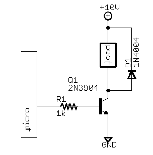
the diode is only needed for motors, solenoids, and other stuff with coils in them
the load is what you want to power and the 10 volts can obviously be changed
From what I remember, the SD card shield from libelium uses digital pin 8 to power the shield. In the sketch, before the SD card starts to be used, the SD shield is enabled by setting pin 8 to high.
This shield does not seem to have a transistor (SD card takes less than 40mA current, I assume).
hmm.. thats exactly what i did (digitalWrite(14,HIGH)).. yet the outcome is different from using the 5V pin...
Just to be clear, you don't say that you set the pin to output first. The pins default to input, so you would want pinMode(14, OUTPUT); before digitalWrite(14, HIGH); as shown on http://www.arduino.cc/en/Tutorial/AnalogInputPins (under heading 'Pin Mapping').
I guess it has to do with only having 40ma...
Was that a guess at what the problem was, or do you know you need more than 40ma?
It could save a lot of mucking about if all it needs is the pinMode(...).
alright - it was only a matter of setting the pinmode to Output(!). Thanks for that tip/obvious hint/putting my nose onto it :0)