int xpin = 34;
int ypin = 35;
int spin = 2;

int xval = 0;
int yval = 0;
int sval = 0;

void setup(){
  Serial.begin(9600);
  pinMode(xpin, INPUT);
  pinMode(ypin, INPUT);
  pinMode(spin, INPUT);
  digitalWrite(spin, HIGH);

}

void loop(){
  xval = analogRead(xpin);
  yval = analogRead(ypin);
  sval = digitalRead(spin);
  delay(200);

  Serial.print("X Value: ");
  Serial.print(xval);
  Serial.print("   Y Value: ");
  Serial.print(yval);
  Serial.print("   Switch State: ");
  Serial.println(sval);

  delay(500);
}
When i open my serial monitor this is what i get:
X Value: 0 Y Value: 0 Switch State: 0
btw I am using ESP32
Welcom and thanks for using code tags in your first post 
Which board are you using? The pins that you are using might not be pins with analogue input capabilities.
J-M-L
3
which one?
(and what did you connect to those pin?)
Are you using 30-pin ESP32 Dev Boad (Fig-1) or 38-pin ESP32 Dev Board (Fig-2)?
Figure-1:
Figure-2:
I am using ESP-WROOM-32 with 38 pins
You mean that you are using Fig-2 of post #4. Better, you post the picture of your board.
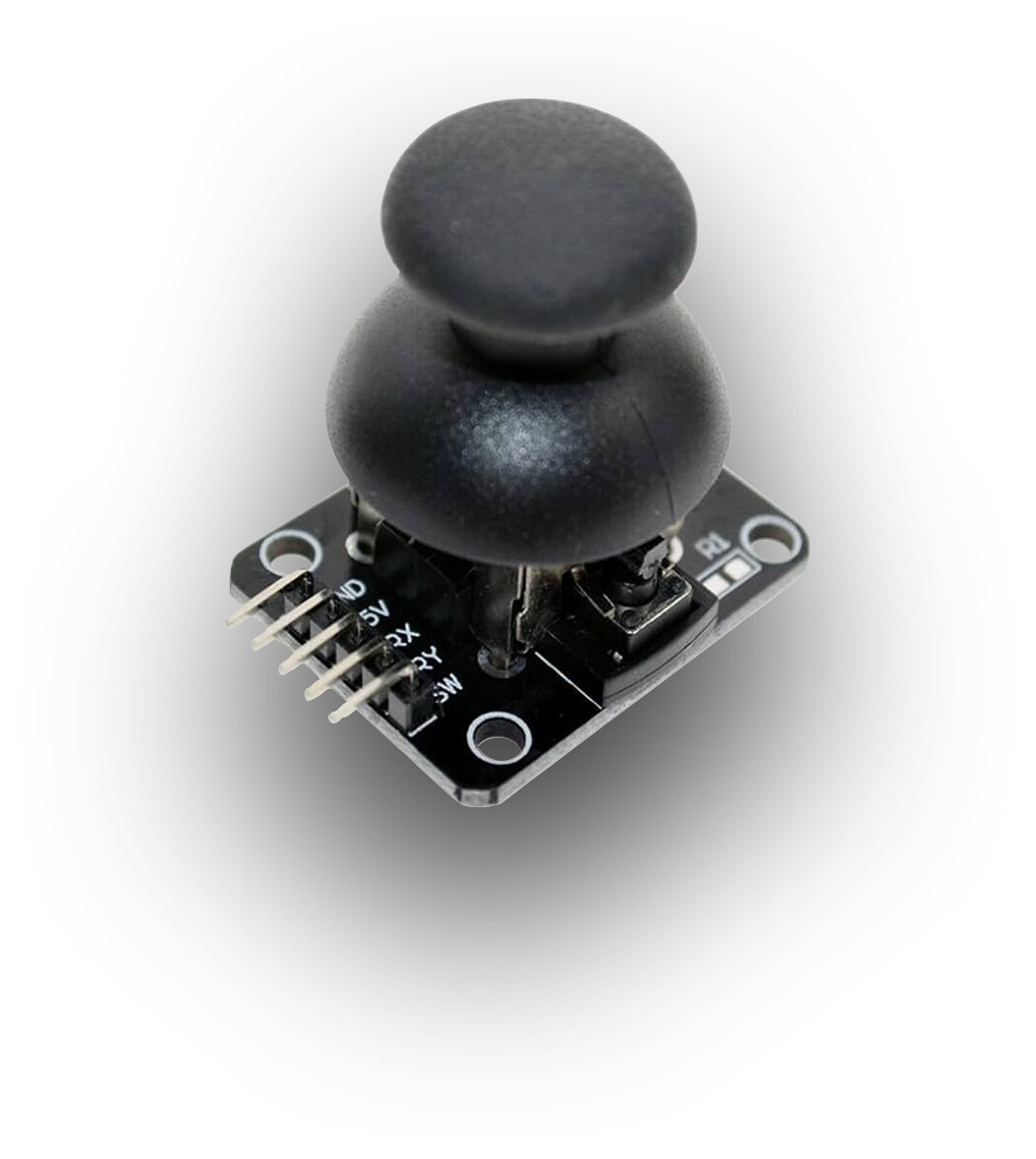
2 axis joystick
GND connected to pin GND
5V+ connected to pin 5V
VRx connected to pin 34
VRy connected to pin 35
SW connected to pin 2
J-M-L
10
what's VRx VRy and SW? which component is on the other side? how is it powered?
VRx, VRy, SW are the pins of my DUAL-Axis XY PS2 Joystick Module
J-M-L
12
can you share a link to te module and a drawing of the circuit?
Does it look like this ?
Hi, @jlsssss
Welcome to the forum.
Can you please post a schematic of your project?
Can you please post some images of your project?
So we can see your component layout?
Thanks.. Tom.. 


@jlsssss
Please, use a DVM Meter and measure the voltage at V5-pin of your ESP32 Board and ensure that it is 5V.
I have tested your sketch of post #1 in my 30-pin ESP32 Dev Board feeding DC signals from Pots. The channels are working except 2.
the DVM Meter reads 5 volts
J-M-L
17
so do you plan to post a drawing of your circuit?
(if you power it with 5V, I'm afraid you'll get 5V back when at full value. your ESP is not designed to accommodate 5V input on its GPIOs)
Disconnect Joystick from the Board.
Connect DPin-34, DPin-35 with 3.3V.
Check that the Serial Moniotr shows: 4095 for both channels.
it shows 4095 for both channels
I've tried using an Arduino UNO board and using this code but still shows same result
int xpin = A0;
int ypin = A1;
int spin = 2;

int xval = 0;
int yval = 0;
int sval = 0;

void setup(){
  Serial.begin(9600);
  pinMode(xpin, INPUT);
  pinMode(ypin, INPUT);
  pinMode(spin, INPUT);
  digitalWrite(spin, HIGH);

}

void loop(){
  xval = analogRead(xpin);
  yval = analogRead(ypin);
  sval = digitalRead(spin);
  delay(200);

  Serial.print("X Value: ");
  Serial.print(xval);
  Serial.print("   Y Value: ");
  Serial.print(yval);
  Serial.print("   Switch State: ");
  Serial.println(sval);

  delay(500);
}