I had a couple other questions that this forum was helpful with (even if one of them was a little more rubber duck debugging), but I've got one final question that has been bugging me a bit. If you want to skip to the real question, it's bolded/underlined a couple paragraphs down. You might not need all the background info I provide about the project.
I've got a project with the need for a couple individual power supplies. Here are the components and their (estimated required) voltage amounts:
- Arduino itself (240mA*)
- 5v relay board w/ 4 relays that require ~80mA apiece (320mA max, all on)
- 5v SSR relay board w/ 8 relays that require ~20mA apiece (80mA max, no more than 3 will be on at once, extra 20mA for good measure)
*For Arduino, I'm considering the amount required to run the board, chip, and any current that would be sent through the I/O pins, which should be very low for most. I think this number is way on the high side, but correct me if I'm off)
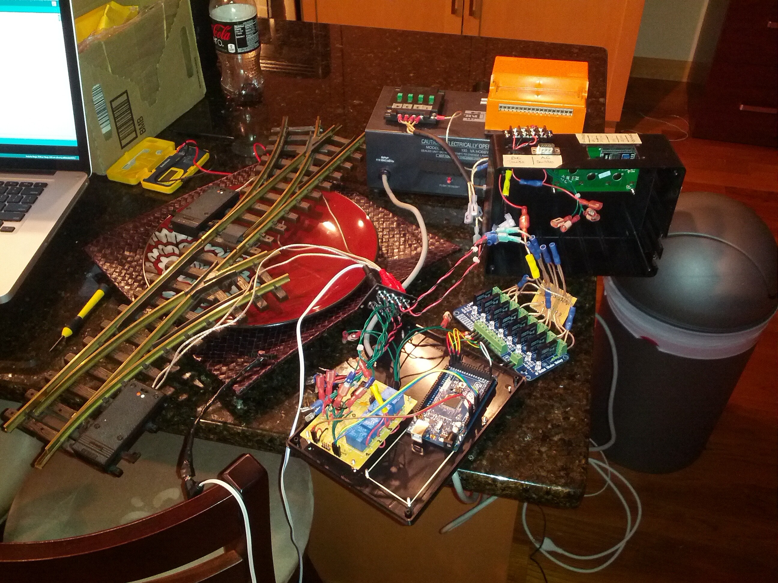
I haven't run a full system test yet, but I've tested all the components together and they seem to be working. But I know they aren't setup well. Right now, the SSR board is powered by the 5v rail of the Arduino and uses the pins for 20mA 200ms pulses, no more than 3 at a time. The mechanical relay board has 4 relays that are all triggered by 3904 transistors from the IO pins, but connected to the 5v rail of the Arduino. Right now there's no need to have more than one active at once, but I would like to change that. An LCD panel is also powered via the 5v rail and uses the SDA/SLC pins. There are also a couple photoresistors I'm using as sensors which use a very negligible current.
So, basically, right now I have a whole bunch of peripherals that are powered via the onboard 5v regulator, and drawing a decent amount of current, which from what I understand isn't fantastic for the board. I'm using a 9v 1000mA wall wart to power the whole kit and kaboodle. I've got a picture of the setup sprawled out attached to this thread.
I've got two of these coming from Amazon: http://www.amazon.com/gp/product/B009HPB1OI/ref=oh_details_o00_s00_i00?ie=UTF8&psc=1, so I don't have to deal with dropping the voltage from 9v to 5v. I probably could have mocked up my own but I'm really at that point where I'd rather just get something that works. Here's the question:
How would you branch off this power supply to reliably power the Arduino and the voltage converter, keeping most of the "guts" inside the project box and maintaining one power connection to the project?
I've read around and saw some solutions suggesting that I can either:
- Tap into the DC power line before the barrel connector and hookup the Arduino via Vin and the voltage converter via the new branch on the power cable.
- Solder leads onto the DC power jack to provide access "after the plug" but "before the diode." This seems really contained, which I like, but a little extreme of a measure.
- Get a DC jack, attach it to the side of the box, and solder two positive and two negative leads to the terminal, sending power to the Arduino and voltage converter. Seems like the best approach, to be honest.
I also don't know if there are other considerations to be made, so if there's anything that you think I might be missing, I'd be incredibly grateful for the help. Like, would I need resistors on each branch to control the amount of current going to the various... subcircuits?
Thanks for any info!