i had problems with noise using an optical encoder when a small 12V motor was running. leads were 20". trying to keep them separate from the motor leads helped, but I feel that passing the inputs thru a pins 2&6 of a 555 timer to provide more hysterisis is really needed.
i'm curious about how you're using Timer1. Shouldn't it generate just a short pulse (1 msec)? is there any need to track the triac state? shouldn't Timer1 be used as a one-shot? shouldn't it be stopped() on the first event?
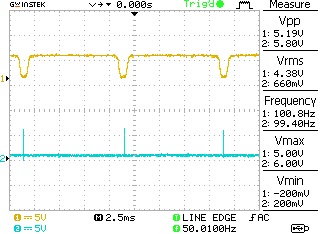
i'm guessing that the yellow trace is pin 3 on the opto and the blue trace a pulse generated within zeroCrossing() that is not in the posted code.
it would be useful to include the triac output waveform (or triac trigger pulse) with either the yellow or blue traces. you would need to see if there are any shifts after confirming the blue and yellow never shift if you haven't done so already
if there is any suspicion about Timer1, you could capture timestamps (micros()) in zeroCrossing() and triacPulse to see if there are any sudden shifts
it is PID. it is tuning the parameters. The PID control gets smoother over time as it finetunes its parameters, but I think a simple PID has some problems with the sine relation between the output (time) and the resulting heating power.
blue is temperature, red is PID output for the Triac period
@gcjr, the hardware works good with fade in fade out sketch - YouTube
PID is often used to control the rate of change of position (i.e. speed) in order to reach with minimal overshoot a desire position. what rate is being controlled? you simply turn the triac on at a specific time
are you suggesting the PID is causing the shifts? if so remove the PID stuff and see if the shifts go away
i suggest you add code to toggle a pin to zeroCrossing() to confirm that the interrupt is synchronized to to the opto output to confirm the external circuitry
you can't make assumption that things work or don't work
I also found on the internet a PID code which works but with problems.
The events are in the following order:
I start the soldering station from AC 230V
The soldering station heats up to maximum (I measure 18mV on the TC at maximum)
I reduce voluntary the temperature by rotating the pot to the minimum
The temperature (and the voltage on the TC) starts to decrease
When the voltage on the TC is about 16-17mV then the power to the soldering iron starts to increase suddenly. And I cannot do anything to make it stable or to decrease it.
The voltage on the TC continues to rise, and when it reaches 22-23mV, I unplug the soldering station from the wall socket, to protect the heater of the soldering iron.
I tried the following solutions for my problem: I checked individually each part of the schematic and all of them were good.
I found that this event happens, when in the code the PID error is equal (=) to set point. This makes the PID value to be 7400 and in the delayMicroseconds(maximum_firing_delay - PID_value); line of code the result is zero (0), making the entire sine wave to be present on the soldering iron heater. I measured those things in serial monitor.
And this is the code:
//Inputs and outputs
int firing_pin = 5;
int zero_cross = 2;

//Variables
int last_CH1_state = 0;
bool zero_cross_detected = false;
int firing_delay = 7400;

//////////////////////////////////////////////////////
int maximum_firing_delay = 7400;
/*Later in the code you will se that the maximum delay after the zero detection
* is 7400. Why? Well, we know that the 220V AC voltage has a frequency of around 50-60HZ so
* the period is between 20ms and 16ms, depending on the country. We control the firing
* delay each half period so each 10ms or 8 ms. To amke sure we wont pass thsoe 10ms, I've made tests
* and the 7400us or 7.4ms was a good value. Measure your frequency and chande that value later */
//////////////////////////////////////////////////////

unsigned long previousMillis = 0;
unsigned long currentMillis = 0;
int temp_read_Delay = 500;
int real_temperature = 0;
int setpoint = 100;

//PID variables
float PID_error = 0;
float previous_error = 0;
float elapsedTime, Time, timePrev;
int PID_value = 0;
//PID constants
int kp = 20;   int ki= 5;   int kd = 10;
int PID_p = 0;    int PID_i = 0;    int PID_d = 0;


void setup() {
//Define the pins
Serial.begin(9600);
pinMode (firing_pin,OUTPUT);
pinMode (zero_cross,INPUT);
PCICR |= (1 << PCIE2);    //enable scan
PCMSK2 |= (1 << PCINT18);  //Set pin D2 (zero cross input) trigger an interrupt on state change.
}


void loop() {
currentMillis = millis();           //Save the value of time before the loop
if(currentMillis - previousMillis >= temp_read_Delay){
previousMillis += temp_read_Delay;              //Increase the previous time for next loop
//get the real temperature in Celsius degrees
// added by Mike
for(int i=0;i<50;i++)
real_temperature += analogRead(A0);
real_temperature /= 50;
real_temperature = map(real_temperature, 0, 550, 25, 400);
// end added by Mike
setpoint = analogRead(A1);
setpoint = map(setpoint, 0, 1023, 150, 400);
PID_error = setpoint - real_temperature;        //Calculate the pid ERROR

if(PID_error > 30)                              //integral constant will only affect errors below 30ºC
{PID_i = 0;}

PID_p = kp * PID_error;                         //Calculate the P value
PID_i = PID_i + (ki * PID_error);               //Calculate the I value
timePrev = Time;                    // the previous time is stored before the actual time read
Time = millis();                    // actual time read
elapsedTime = (Time - timePrev) / 1000;
PID_d = kd*((PID_error - previous_error)/elapsedTime);  //Calculate the D value
PID_value = PID_p + PID_i + PID_d;                      //Calculate total PID value

//We define firing delay range between 0 and 7400. Read above why 7400!!!!!!!
if(PID_value < 0) // initial it was <
{      PID_value = 0;       }
if(PID_value > 7400) // initial it was >
{      PID_value = 7400;    }
previous_error = PID_error; //Remember to store the previous error.
//    Serial.println("PID_error=");
//    Serial.println(PID_error);
//    Serial.println("real_temperature=");
//    Serial.println(real_temperature);
//    Serial.println("setpoint=");
//    Serial.println(setpoint);
//    Serial.println("PID_value=");
//    Serial.println(PID_value);
}

//If the zero cross interruption was detected we create the 100us firing pulse
if (zero_cross_detected)
{
  delayMicroseconds(maximum_firing_delay - PID_value); //This delay controls the power
  digitalWrite(firing_pin,HIGH);
  delayMicroseconds(100);
  digitalWrite(firing_pin,LOW);
  zero_cross_detected = false;
}
}

//This is the interruption routine (pind D8(zero cross), D11(increase) and D12(decrease))
//----------------------------------------------

ISR(PCINT2_vect){
///////////////////////////////////////Input from optocoupler
if(PIND & B00000010){            //We make an AND with the state register, We verify if pin D2 is HIGH???
if(last_CH1_state == 0){       //If the last state was 0, then we have a state change...
  zero_cross_detected = true;  //We have detected a state change! We need both falling and rising edges
}
}
else if(last_CH1_state == 1){    //If pin 2 is LOW and the last state was HIGH then we have a state change
zero_cross_detected = true;    //We haev detected a state change!  We need both falling and rising edges.
last_CH1_state = 0;            //Store the current state into the last state for the next loop
}
}
gcjr:
i suggest you add code to toggle a pin to zeroCrossing() to confirm that the interrupt is synchronized to to the opto output to confirm the external circuitry
you can't make assumption that things work or don't work
again. the hardware works good with a 'fade' sketch
This is a chart. Please have a look.
Chart temperature - the "sine wave" happens when I rotate the pot to minimum temperature.
The temperature increases when the delayMicroseconds(maximum_firing_delay - PID_value); is equal to 0 Microseconds, and I think that this happens right in the moment when pid_values are 7400 (read from the graph).
you have to look at the values in detail. the 11000 in period = 11000 - (75 * output) was only to show that the output works the other way. it should be 10000 microseconds and maybe the 75 should be changed to get the values between 9800 and 1200.
//Inputs and outputs
int firing_pin = 5;
int zero_cross = 2;

//Variables
int last_CH1_state = 0;
bool zero_cross_detected = false;
int firing_delay = 7400;

//////////////////////////////////////////////////////
int maximum_firing_delay = 7400;
/*Later in the code you will se that the maximum delay after the zero detection
 * is 7400. Why? Well, we know that the 220V AC voltage has a frequency of around 50-60HZ so
 * the period is between 20ms and 16ms, depending on the country. We control the firing
 * delay each half period so each 10ms or 8 ms. To amke sure we wont pass thsoe 10ms, I've made tests
 * and the 7400us or 7.4ms was a good value. Measure your frequency and chande that value later */
//////////////////////////////////////////////////////

unsigned long previousMillis = 0;
unsigned long currentMillis = 0;
int temp_read_Delay = 500;
int real_temperature = 0;
int setpoint = 100;

//PID variables
float PID_error = 0;
float previous_error = 0;
float elapsedTime, Time, timePrev;
int PID_value = 0;
//PID constants
int kp = 30;   int ki= 10;   int kd = 5;
int PID_p = 0;    int PID_i = 0;    int PID_d = 0;


void setup() {
  //Define the pins
  Serial.begin(9600);
  pinMode (firing_pin,OUTPUT);
  pinMode (zero_cross,INPUT);
  PCICR |= (1 << PCIE2);    //enable scan
  PCMSK2 |= (1 << PCINT18);  //Set pin D2 (zero cross input) trigger an interrupt on state change.
}


void loop() {
  currentMillis = millis();           //Save the value of time before the loop
  if(currentMillis - previousMillis >= temp_read_Delay){
    previousMillis += temp_read_Delay;              //Increase the previous time for next loop
    //get the real temperature in Celsius degrees
    // added by Mike
    for(int i=0;i<50;i++)
    real_temperature += analogRead(A0);
    real_temperature /= 50;
    real_temperature = map(real_temperature, 0, 550, 25, 400);
    // end added by Mike
    setpoint = analogRead(A1);
    setpoint = map(setpoint, 0, 1023, 150, 400);
    PID_error = setpoint - real_temperature;        //Calculate the pid ERROR

    if(PID_error > 30)                              //integral constant will only affect errors below 30ºC
    {PID_i = 0;}

    PID_p = kp * PID_error;                         //Calculate the P value
    PID_i = PID_i + (ki * PID_error);               //Calculate the I value
    timePrev = Time;                    // the previous time is stored before the actual time read
    Time = millis();                    // actual time read
    elapsedTime = (Time - timePrev) / 1000;
    PID_d = kd*((PID_error - previous_error)/elapsedTime);  //Calculate the D value
    PID_value = PID_p + PID_i + PID_d;                      //Calculate total PID value

    //We define firing delay range between 0 and 7400. Read above why 7400!!!!!!!
    if(PID_value < 0) // initial it was <
    {      PID_value = 0;       }
    if(PID_value > 7400) // initial it was >
    {      PID_value = 7400;    }
    previous_error = PID_error; //Remember to store the previous error.

    Serial.print(PID_error);
    Serial.print(";");
    Serial.print(real_temperature);
    Serial.print(";");
    Serial.print(setpoint);
    Serial.print(";");
    Serial.print(PID_value);
    Serial.println(";");
  }

  //If the zero cross interruption was detected we create the 100us firing pulse
  if (zero_cross_detected)
    {
      delayMicroseconds(maximum_firing_delay - PID_value); //This delay controls the power
      digitalWrite(firing_pin,HIGH);
      delayMicroseconds(100);
      digitalWrite(firing_pin,LOW);
      zero_cross_detected = false;
    }
}

//This is the interruption routine (pind D8(zero cross), D11(increase) and D12(decrease))
//----------------------------------------------

ISR(PCINT2_vect){
  ///////////////////////////////////////Input from optocoupler
  if(PIND & B00000100){            //We make an AND with the state register, We verify if pin D2 is HIGH???
    if(last_CH1_state == 0){       //If the last state was 0, then we have a state change...
      zero_cross_detected = true;  //We have detected a state change! We need both falling and rising edges
    }
  }
  else if(last_CH1_state == 1){    //If pin 2 is LOW and the last state was HIGH then we have a state change
    zero_cross_detected = true;    //We haev detected a state change!  We need both falling and rising edges.
    last_CH1_state = 0;            //Store the current state into the last state for the next loop
    }
}