// Initialize the Serial connection to the debug computer:
Debug.begin( debugBaud );
// Initialize the SPI connection:
SPI.begin();
SPI.setClockDivider( SPI_CLOCK_DIV2 ); // Must be less than 10MHz.
// Initialize the MAX7456 OSD:
OSD.begin(); // Use NTSC with default area. //OSD.setCharEncoding( MAX7456_ASCII ); // Only needed if ascii font.
OSD.display(); // Activate the text display.
}
// setup()
// Main Code ///////////////////////////////////////////////////////////////////
void loop()
{
while (OSD.notInVSync()); // Wait for VSync to start to
// prevent write artifacts.
OSD.print( "Hello World!" ); // The '!' will not display
// because it does not come
// in the factory font.
while (true);
I have connected a currentSensor to Arduino Mega 2560,I use Analog Pin A0
It`s working,after I have remove the while (true); from the void loop.
With while (true); the numbers(reading) on osd standstill, sow you will not get any reading,and is no flicker on screen.
without the while (true); you will get reading,but you will also get some flicker on the screen(the numbers) ,why?
I need to have mAh,after the numbers,how can i do that in the code?
I have newer use any Arduino or programming before.
Here is the code:
// Included Libraries //////////////////////////////////////////////////////////

  #include <SPI.h>
  #include <MAX7456.h>

// Pin Mapping Of MAX7456 /////////////////////////////////////////////////////////////////

  const byte osdChipSelect             = 43;
  const byte masterOutSlaveIn          = 51;
  const byte masterInSlaveOut          = 50;
  const byte slaveClock                = 52;
  const byte osdReset                  = 0;

// Global Variables ////////////////////////////////////////////////////////////

MAX7456 OSD( osdChipSelect );
const int numReadings = 30;
float readings[numReadings];      // the readings from the analog input
int index = 0;                  // the index of the current reading
float total = 0;                  // the running total
float average = 0;                // the average

float currentValue = 0;

// Hardware Setup //////////////////////////////////////////////////////////////

  void setup()       // Initialize the SPI connection:
  {
    SPI.begin();
    SPI.setClockDivider( SPI_CLOCK_DIV2 );      // Must be less than 10MHz.

    // Initialize the MAX7456 OSD:
    OSD.begin();                                // Use NTSC with default area.
    //OSD.setCharEncoding( MAX7456_ASCII );       // Only needed if ascii font.
    OSD.display();                              // Activate the text display.
    for (int thisReading = 0; thisReading < numReadings; thisReading++)
    readings[thisReading] = 0;

  }

// Main Code ///////////////////////////////////////////////////////////////////

  void loop()
  {
    total= total - readings[index];
    readings[index] = analogRead(0); //Raw data reading
    readings[index] = (readings[index]-510)*5/1024/0.04-0.04;//Data processing:510-raw data from analogRead when the input is 0; 5-5v; the first 0.04-0.04V/A(sensitivity); the second 0.04-offset val;
    total= total + readings[index];
    index = index + 1;
    if (index >= numReadings)
      index = 0;
    average = total/numReadings;   //Smoothing algorithm (http://www.arduino.cc/en/Tutorial/Smoothing)
    currentValue= average;
    OSD.setCursor(6,5);
    OSD.print(currentValue);
    delay(30);


  }
Interrupt jitter. Most instructions on Atmel AVRs take anywhere from 1 to several clock cycles to complete and an interrupt will not fire until a full instruction is complete. So your interrupt might fire a little late or a lot late depending on what's being executed at that particular moment. This unstable timing leads to OSD rows that don't quite line up.
If you don't want to use while(true) to eliminate interrupt jitter, you can do whatever you need to do and then go into sleep mode at the end of your loop(). If the processor is asleep when the interrupt fires, there will be no lag because there won't be any active instructions. This should eliminate the jitter as long as you don't take more time than the horizontal blanking interval allows.
The problem here is an analogRead() takes too long (100 microseconds). Try it, but if you still get jitter, you will need abandon analogRead and instead use AVR C to start an asynchronous ADC conversion and then poll the ADC completion register (don't enable the ADC completion interrupt vector or you'll be right back into jitter territory).
I have no ide how i can do that,possible for you to do that with this code?
I am newbie.,i dont have so much knowledge about Programming.
But,you can not use the while(true),when somthing change all time?(example this 50A Current Sensor)
I need to have mAh,after the numbers,how can i do that in the code.
I have figured it out
// Included Libraries //////////////////////////////////////////////////////////

  #include <SPI.h>
  #include <MAX7456.h>

// Pin Mapping Of MAX7456 /////////////////////////////////////////////////////////////////

  const byte osdChipSelect             = 53;
  const byte masterOutSlaveIn          = 51;
  const byte masterInSlaveOut          = 50;
  const byte slaveClock                = 52;
  const byte osdReset                  = 0;

// Global Variables ////////////////////////////////////////////////////////////

MAX7456 OSD( osdChipSelect );
const int numReadings = 30;
float readings[numReadings];      // the readings from the analog input
int index = 0;                  // the index of the current reading
float total = 0;                  // the running total
float average = 0;                // the average

float currentValue = 0;

// Hardware Setup //////////////////////////////////////////////////////////////

  void setup()       // Initialize the SPI connection:
  {
    SPI.begin();
    SPI.setClockDivider( SPI_CLOCK_DIV2 );      // Must be less than 10MHz.

    // Initialize the MAX7456 OSD:
    OSD.begin();                                // Use NTSC with default area.
    //OSD.setCharEncoding( MAX7456_ASCII );       // Only needed if ascii font.
    OSD.display();                              // Activate the text display.
    for (int thisReading = 0; thisReading < numReadings; thisReading++)
    readings[thisReading] = 0;

  }

// Main Code ///////////////////////////////////////////////////////////////////

  void loop()
  {
    total= total - readings[index];
    readings[index] = analogRead(0); //Raw data reading
    readings[index] = (readings[index]-510)*5/1024/0.04-0.04;//Data processing:510-raw data from analogRead when the input is 0; 5-5v; the first 0.04-0.04V/A(sensitivity); the second 0.04-offset val;
    total= total + readings[index];
    index = index + 1;
    if (index >= numReadings)
      index = 0;
    average = total/numReadings;   //Smoothing algorithm (http://www.arduino.cc/en/Tutorial/Smoothing)
    currentValue= average;
    OSD.setCursor(6,5);
    OSD.print(currentValue);
    delay(30);
    OSD.setCursor(12,5);
    OSD.print("mAh");

  }
Hi Ingenn
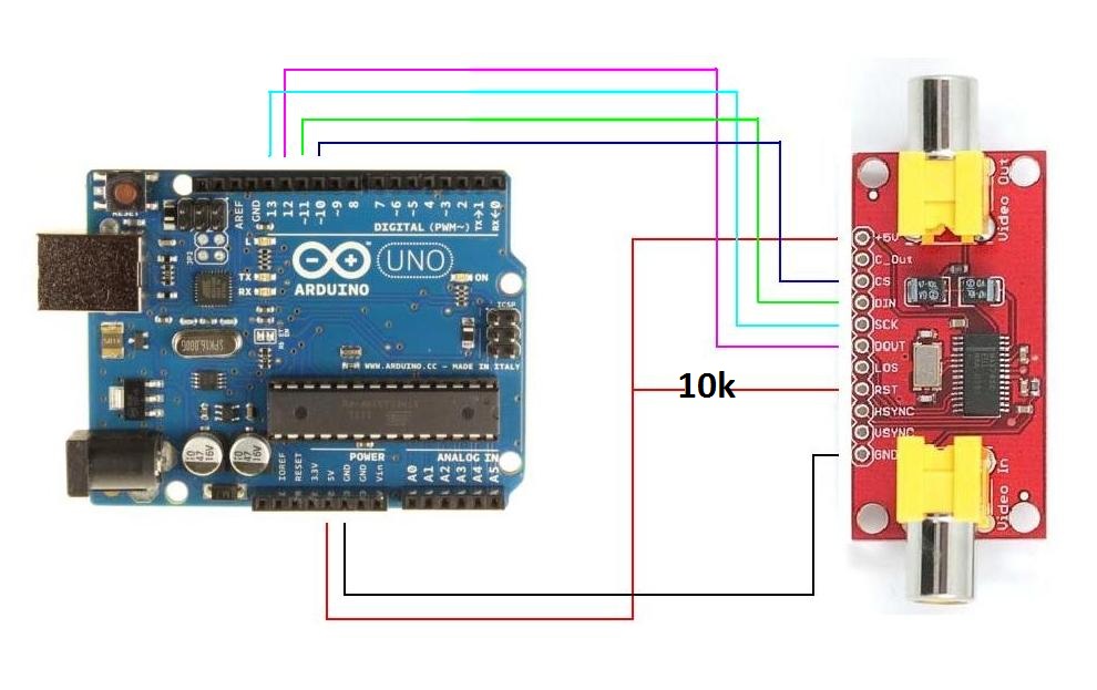
Was wondering what hardware/schematic do you use to have this osd code working(i just changed the pin numbers to match uno 10,11,13,12). I tryed with minim osd board and it's not overlaying anything, tried with arduino uno and max7456 bob and still not displaying anything. Atached is wiring diagram i used.
Thanks buddy
I have now try,but I do not understand, how to add this in the code?
Here is a movie of the osd in action:
// Included Libraries //////////////////////////////////////////////////////////

  #include <SPI.h>
  #include <MAX7456.h>

// Pin Mapping Of MAX7456 /////////////////////////////////////////////////////////////////

  const byte osdChipSelect             = 43;
  const byte masterOutSlaveIn          = 51;
  const byte masterInSlaveOut          = 50;
  const byte slaveClock                = 52;
  const byte osdReset                  = 0;

// Global Variables ////////////////////////////////////////////////////////////

MAX7456 OSD( osdChipSelect );
const int numReadings = 30;
float readings[numReadings];      // the readings from the analog input
int index = 0;                  // the index of the current reading
float total = 0;                  // the running total
float average = 0;                // the average

float currentValue = 0;

// Hardware Setup //////////////////////////////////////////////////////////////

  void setup()       // Initialize the SPI connection:
  {

    SPI.begin();
    SPI.setClockDivider( SPI_CLOCK_DIV2 );      // Must be less than 10MHz.

    // Initialize the MAX7456 OSD:
    OSD.begin();                                // Use NTSC with default area.
    //OSD.setCharEncoding( MAX7456_ASCII );       // Only needed if ascii font.
    OSD.display();                              // Activate the text display.
    for (int thisReading = 0; thisReading < numReadings; thisReading++)
    readings[thisReading] = 0;

  }

// Main Code ///////////////////////////////////////////////////////////////////

  void loop()
  {
    total= total - readings[index];
    readings[index] = analogRead(0); //Raw data reading
    readings[index] = (readings[index]-510)*5/1024/0.04-0.04;//Data processing:510-raw data from analogRead when the input is 0; 5-5v; the first 0.04-0.04V/A(sensitivity); the second 0.04-offset val;
    total= total + readings[index];
    index = index + 1;
    if (index >= numReadings)
      index = 0;
    average = total/numReadings;   //Smoothing algorithm (http://www.arduino.cc/en/Tutorial/Smoothing)
    currentValue= average;
    OSD.setCursor(6,5);
    OSD.print(currentValue);
    delay(30);
    OSD.setCursor(12,5);
    OSD.print("mAh");
   OSD.setCursor(12,7);
    OSD.print("TEST");
    OSD.setCursor(12,9);
    OSD.print("THIS IS A TEST");
    OSD.setCursor(2,8);
    OSD.print("HELLO");
    OSD.setCursor(2,6);
    OSD.print("HELLO");


  }
To Supercln.
You need to use a 10K resistor from 5v to RST.
Forgot to say,you also need to use a 120ohm resistor between GND and CS = ChipSelect on MAX7456,with this libraries,i dont know why.
Hi Ingenn
Thanks for your reply. I haven't had time to play with it for a while, but here i am again.
I have tried as you said 10K and 120ohms resistors and still nothing displays when there's a video in.
When i turn off the video source i get the overlay on a grey screen.(see atached pic) this is with the lib and code/wiring from this page.
Any ideeas?
I'm using PAL, do't know if this is the issue.
Thanks