Thanks for pointing it out, I made this error sorry, the other four pins are connected to the nano
Alright, so how do you se the input values on the 2x4 pins?
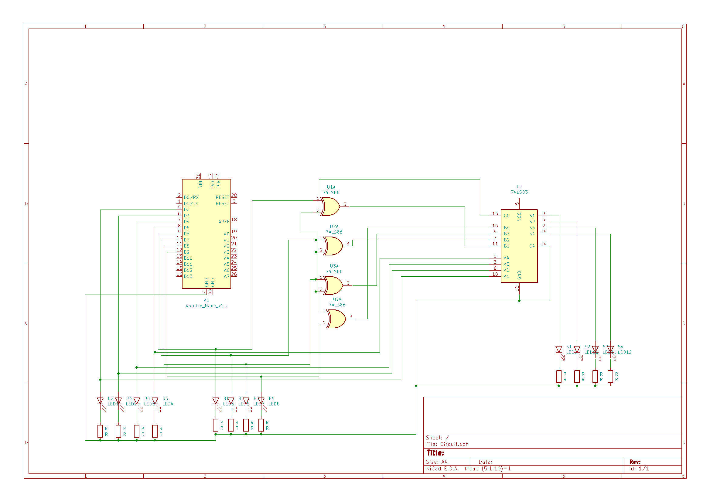
But why are the LEDs connected to input pins? They should be connected to output pins. And now that he has posted a schematic, LEDs 1-4 are being driven from the microcontroller, so LED1Pin through LED4Pin should certainly be OUTPUT. However LEDs 5-8 are being driven from the inputs of the exor gates??? No way that will work. They need to also be driven from the microcontroller. I guess the EXOR gates are to switch between add and subtract, so there should also be an output from the microcontroller that goes to all the EXOR gates.
So there should be 9 outputs from the microcontroller and no inputs. Eight go to two sets of 4 LEDs ("A" and "B"). The A set connects to the A inputs of the adder, the B set to the exclusive or gates along with the 9th output of the microcontroller. The four outputs of the EXOR gates go to the B inputs of the adder. The S0 input of the adder comes from the 9th output of the microcontroller. The S outputs of the adder go to the sum LEDs, of which there there should be five, to include the C4 output which is the 5th sum bit. Most assuredly, the C4 output should not be connected to ground.
Yup, this is one confused project for sure. I can imagine something with pins acting altetnatingly as inputs and outputs, but the current hardware doesn't support it, but has this set of logic devices that seem a bit redundant to me in the presence of a Nano.
OP, perhaps give this one another thorough think-through, because it seems your plan is rather inconsistent.
I mean it is should be a binary calculator after all or not? With 8 leds for input and 4 leds for output, you really can't do that with the setup? Do you have any tips how I should do it differently?
It's a fun project, but it seems to me you're confusing two fundamentally different approaches. One approach is using hardware logic ports such as those on the right hand side of your schematic. You don't need an Arduino at all in that case.
The other approach is basically replacing the logic ports with a microcontroller such as an Arduino. In that case you don't need the IC's on the right half of your schematic.
In both cases you'll have to think of input and output -how does the user enter the values, and how does she read the outcome? You (sort of) have the output covered, but on the input side you're running aground because of the mixed up approach.
The Input of the user would come from the serial monitor aswell as the output like 1+2=3, for that you would see the A leds and B leds light up with A=1 and B=2 binary, and the sum of both would light up as binary 3 in S. Can you give me a hint on how to solve my issue? I mean im kinda lost at this point...
Like I said, you're mixing up two approaches. If you want to use serial input, then use that for the calculation and don't read those pins. If you use serial as the input, you don't need to have any input pins whatsoever. The only leds you'd have are outputs that show the result of the calculation. You also don't need those additional IC's in addition to your nano. You can do what you want with just one nano, 4 resistors and 4 leds if you only want to show the output, or 12 resistors and 12 leds if you want to show both operands and the outcome simultaneously. Forget about the XOR ports and LS logic chips and whatnot for now.
Okay thanks for the answer and for the help! I will try your approach.
Hi,
Thanks for the schematic. ![]()
Have you just written code to light up your LEDs to prove they work.
Forget about the XOR and ADDER, pull them out of the protoboard and write some code to prove that ALL your LEDs work.
Do you have a DMM?
Did you write your code in stages?
Have you got code that just shows that you are getting the correct Serial Input Data?
Tom.... ![]()
![]()
![]()
![]()
Hi,
Can I suggest you start like this, with giving your pin names some meaning and assign your bit values on your schematic.
int A8Pin = 5; // Byte A MSB to LSB
int A4Pin = 4;
int A2Pin = 3;
int A1Pin = 2 ;

int B8Pin = 9; // Byte B MSB to LSB
int B4Pin = 8;
int B2Pin = 7;
int B1Pin = 6;

void setup()
{
  Serial.begin(9600);
  Serial.println("calculate:");
  pinMode(A1Pin, OUTPUT);
  pinMode(A2Pin, OUTPUT);
  pinMode(A4Pin, OUTPUT);
  pinMode(A8Pin, OUTPUT);
  pinMode(B1Pin, OUTPUT);
  pinMode(B2Pin, OUTPUT);
  pinMode(B4Pin, OUTPUT);
  pinMode(B8Pin, OUTPUT);


}

void loop()
{


}

Tom.... ![]()
![]()
![]()
![]()
Hey, thanks for the answer but I got my circuit to work with xor and the adder, I used the two parameters A and B as integer and limited the numerical value to -8 to 7, in order to recognize the input of A and B I use this part of the code:
      //A
int A;
      if (input[0] == '-' || input[0] == '+')
      {
        if (input[1] >= '0' && input[1] <= '8')
        {
         A = input[1] - '0';
         A_pos = 1;
         if (input[0] == '-')
         {
          A = A * -1;
         }
        }
      }
      //2. Fall Zahl an der ersten Stelle
      else if (input[0] >= '0' && input[0] <= '8')
      {
        A = input[0] - '0';
        A_pos = 0;
      }
int B;
      //B
      if (input[A_pos + 2] == '-' || input[A_pos + 2] == '+')
      {
        if (input[A_pos + 3] >= '0' && input[A_pos + 3] <= '8')
        {
         B = input[A_pos + 3] - '0';
         if (input[A_pos + 2] == '-')
         {
          B = B * -1;
         }
        }
      }
And for the Xor and adder I worte this:
    for(int n=3; n >= 0; n--){                  //n to save Bitinfo
     if (bitRead(A, n) == true){
      digitalWrite(ledPinsA[n], HIGH);
      }

     if(operator1 == '-'){
      digitalWrite(XOR, HIGH);
     }
     else if (operator1 == '+') {
      digitalWrite(XOR, LOW);
     }


     if (bitRead(B, n) == true) {
      digitalWrite(ledPinsB[n], HIGH);}

int calculate(int a, int b, int c) {

  if(c == '+') { return a+b;}
  if(c == '-') { return a-b;}
Of course there is additional some code between those lines, but these are the important ones for me. All of it works like I wanted it too do. Thanks for all the help I really appreciate the quick responses.