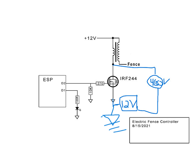
I found this image from @SteveMann in a old post. I would like to create something exactly like this only I was intending to use a bib373 or equivalent replacement as the switch to ground.
Does anyone see any problems with this design to power a 20K coil from a 12V battery. I believe I need a coil that does not have internal resistance and that I need to place a capacitor across the - on the coil and - on the battery from reading on this Forum. I saw someone recommend a 400V capacitor.
I also wonder why D1 is to ground?
The problem, if that is really connected to a fence wire, is that the opposite side needs to be connected to the fence ground, not to 12 volts! You ALSO need to short the fence wire to ground after so many milliseconds in order to discharge the voltage in the fence/ground capacitor.
As I understand it (And remember I am asking because I may not understand it correctly) is that on the primary side of the coil the positive side it connected to 12V+ from the battery. The negative side of the coil gets connected to 3 items: a 400Volt capacitor, the "pulsing switch", and the earth ground.
The "pulsing switch" is a IRF or BiIB373 that is triggered by the Arduino.
The center point or secondary of the coil is connected to the fence.
The law in the US, anyway, limits the pulse to once per second and only a fraction of that second, so the fence capacitor must also be discharged in your control unit. That is why they ALWAYS make a click when they discharge. Otherwise a child gripping the wire would never have a chance to release the wire.
2 Likes
ok so my schematic works if we have gotten to the point of talking about the law? Or is there something incorrect with the schematic that I dont understand. I know that the schematic is poorly drawn onto.
I intend to set the pulsing using the arduino. I understand I could also use a 555 timer but the arduino allows me to connect LORA and remotely turn it off/on.
You could also turn off a 555 timer using the Arduino. Test your circuit!
It is to light up an LED.
I believe I need a coil that does not have internal resistance
They all do. It is the coil resistance that limits the current draw.
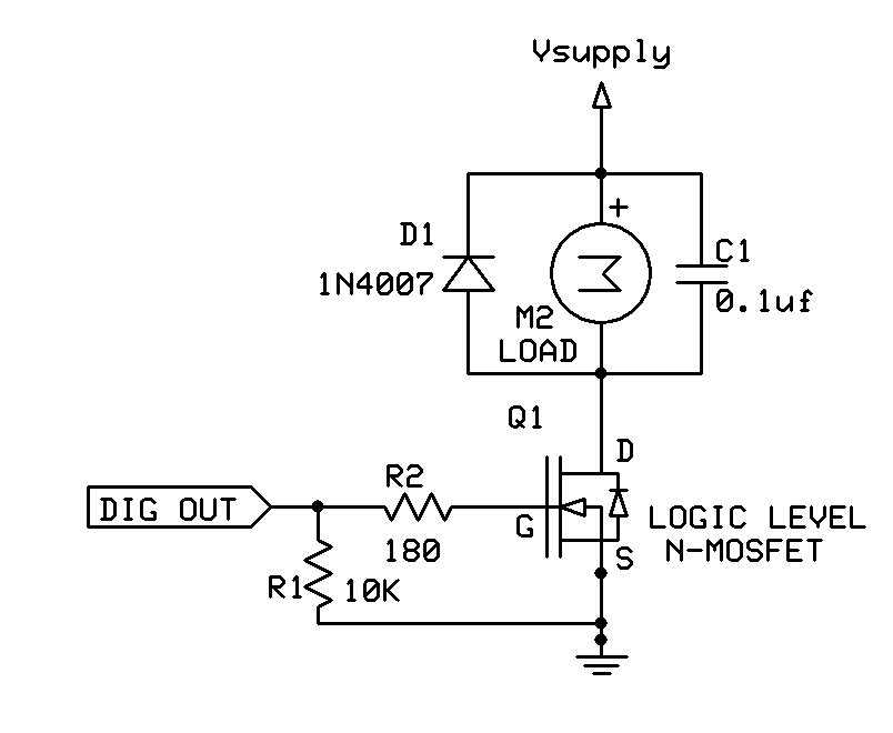
The IRF244 probably won't work in that circuit. You need a logic level MOSFET instead, especially with the 3V output from the ESP MCU.
You also need a diode across the primary (low voltage) coil to protect the transistor from the inductive turnoff spike. It does not need to be a high voltage diode.
The same basic idea is required for motor and solenoid control circuits:
Finally, if the negative side of the 12V battery is grounded, then that effectively grounds the secondary (high voltage) coil.
Thanks for the help.
I apologize about the foolish LED question that makes perfect sense.
As for the coils some are advertised as internally, and others externally resisted. Understanding the nature of a coil makes some resistance I specifically was thinking I wanted one that did not have additional resistance.
I understand the diode. Using your example, I install a 1N4007 from the +12v side of the coil to the -12v side of the coil. Duly noted.
I need to figure out a different mofset. ISL9v5036s3s was what I was thinking about using but had not gotten a chance to study the spec sheet on voltage. I read somewhere a "standard" (what ever that means) mofset can burn up easily. Maybe the diode would take care of that.
Lastly the - on the coil, capacitor, transistor would all be connected to 3 earth ground rods 8' long and 10' apart.
I really don't know what this means, although I can imagine that a resistor is required to limit the coil current to a specific value, in which case you need to know what that current value is.
Are these coils specifically designed for electric fences? Please post links to both types of coils.
This is an example of a logic level MOSFET that will work in that circuit.
Presumably the resistor is required to protect the coil from overcurrent. Use it.
I found this comment on a discussion forum
Quite a few ignition coils can be damaged (burning up) if the ignition is left on wihout the engine running. The use of a series ballast resistor keeps the currnt down under those conditions. Most, if not all 12 volt ignition systems have either a resistor mounted somewhere in the engine compartment or its resistance wire built in the harness. When running, the coil sctually runs on about 8 volts.
The starter solenoid has a shorting switch on some cars, which shorts out the ballast resistor while the starter is running.
1 Like
Understood. I was led to believe once that if using a coil on a vehicle that has points you need to use it because you run the risk of arching the points if the voltage goes to high and if you had a vehicle that did not need points then the higher voltage would help burn fuel cleaner.
Buy really, I am not a motor guy Ive only restored 1 tractor motor ever! So I just do as I am told by others.
Hi,
If you are building an electric fence then check your country's, state gov, local gov regulations on them.
Some countries including Australia have a standard that a Fencer should perform too, this is not just to preserve life but prevent bushfires.
Here is an example and check list.
Ignition coils are not recommended.
Tom... 


PS. So forget about using a Ford Model T coil...
1 Like
And you have not mentioned, but remember that an automotive coil creates the high voltage when the primary circuit is opened, not when current is flowing to create the magnetic field.
I haven't updated the schematic, but I used the IRL540 (logic-level Mosfet) in my final design.
The original design was to keep chipmunks out of my tomato garden, not to kill them. In this design I used a small engine spark transformer that was intended for a 12V garden vehicle. And it was cheap on eBay.
The output is about 300V. Enough to scare the chipmunks without doing any damage. I can touch the HV wire easily.
The IRL540 has a flyback diode built-in, so you don't need one across the coil.
Internal or external resistor. There seems to be some confusion here. The spark resistance is to limit the spark current. Too high and you will generate a lot of ignition noise. Which is noticeable on the radio and could probably play havoc with an ESP or Arduino.. Spark plug wires are typically high resistance, about 10K per foot, for this reason. I used no series resistor and the ESP has been running for hundreds of hours.
You have not shown how you intend to discharge the high voltage capacitor created by you high voltage fence wire.