Hello to everyone!
I'm trying to modify a model train with an Arduino Nano and I'm having some problems with a digital pin set as INPUT_PULLUP not going to LOW when I connect it to GND.
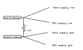
I attach the code and a schematic below, the basic idea is that the Arduino Nano has to receive commands to start / stop / change speed via Bluetooth from the HC-05, and drive the motor in the model train through the L293D chip. The power supply consists of a 18650 battery holder with two cells connected in series. Also, the model train has to detect magnets along the tracks with a reed switch, and send a message over Bluetooth when is does. To do this, I set the pin D2 as INPUT_PULLUP, connected D2 to one of the sides of the switch, and the other to ground.
The problem is that when I turn on the motor, there is no way to make the pin D2 (connected to the reed switch) to get LOW, even connecting it directly (or through a resistor) to GND doesn't make it LOW, and so it doesn't trigger the interrupt (I also tried checking if it’s LOW in the loop function, but no use). However, if I stop the motor, the this problem goes away and the interrupt and reed switch work every time.
So far I’ve tried to use a 5.2KOhm resistor between the output of the switch and GND (works when the motor is stopped, otherwise also no), I’ve tried putting a 5.2KOhm resistor between D6 and the L293D, and D7 and the L293D, and a 10Ohm resistor between D5 (PWM) and the PWM input of the L293D (which also slowed down the motor), but the problem on D2 persists.
What am I missing?
//
// Pinout description: (ARDUINO UNO / NANO)
// DIGITAL:
// 2 } - Reed switch
// 3
// 4
// 5   } - L293D - { Enable
// 6   }           { DIR_B
// 7   }           { DIR_A
// 8
// 9
// 10
// 11
// 12
// 13
// TX -> HC-05 RX
// RX -> HC-05 TX


// Constants
const unsigned long ACCESS_KEY = 2107106630;
const byte MOTOR_MAX_POWER = 100;
const byte MOTOR_MIN_POWER = 85;
const float MAX_SPEED_LIMIT = 255;
const unsigned short SOFTWARE_DEBOUNCING_WAIT = 250; // ms

// Define pinout
const byte REED_SWITCH_PIN = 2;

const byte MOTOR_ENABLE_PIN = 5;
const byte MOTOR_DIR_A_PIN = 6;
const byte MOTOR_DIR_B_PIN = 7;

const unsigned short SERIAL_BAUD_RATE = 57600;

// Variables
volatile bool reedSwitchClosed = false;
volatile long lastReedSwitchClosedTime = 0;


enum CommunicationMessageServerToClient {
  FORWARD = 1,
  BACKWARD = 2,
  FAST_STOP = 3
};

enum CommunicationMessageClientToServer {
  REED_TRIGGERED = 1,
};

void setup()
{
  // Initialize the pin and interrupt for the reed switch
  pinMode(REED_SWITCH_PIN, INPUT_PULLUP);
  attachInterrupt(digitalPinToInterrupt(REED_SWITCH_PIN), onReedSwitchClosed, FALLING);

  // Initialize the pins for the L293D motor controller
  pinMode(MOTOR_ENABLE_PIN, OUTPUT);
  pinMode(MOTOR_DIR_A_PIN, OUTPUT);
  pinMode(MOTOR_DIR_B_PIN, OUTPUT);

  // Open a (hardware) serial connection with the HC-05 BlueTooth module
  Serial.begin(SERIAL_BAUD_RATE);
  // Log in the the ground control software through BlueTooth
  blueToothLogin();
}

void blueToothLogin()
{
  // When the ground control server is ready, it sends a byte of all ones (255) and awaits for the token
  // Wait for the "ready" byte to come
  while (Serial.available() == 0) {}
  Serial.read();
  // Send the authentication token
  Serial.write((byte*)&ACCESS_KEY, sizeof(unsigned long));
}

void onReedSwitchClosed()
{
  if (millis() - lastReedSwitchClosedTime < SOFTWARE_DEBOUNCING_WAIT)
  {
    lastReedSwitchClosedTime = millis();
    return;
  }
  lastReedSwitchClosedTime = millis();
  reedSwitchClosed = true;
}

void loop()
{
  if (reedSwitchClosed)
  {
    Serial.write(1);
    Serial.write(CommunicationMessageClientToServer::REED_TRIGGERED);
    reedSwitchClosed = false;
  }

  while (Serial.available())
  {
    receiveIncomingCommunicationMessage();
  }
}

void receiveIncomingCommunicationMessage()
{
  byte size = Serial.read();
  byte message[size];

  for (byte i = 0; i < size; i++) {
    int b = Serial.read();
    if (b == -1)
    {
      i--;
    }
    else
    {
      message[i] = b;
    }
  }

  processIncomingMessage(message);
}

void processIncomingMessage(byte message[])
{
  switch (message[0])
  {
    case CommunicationMessageServerToClient::FORWARD:
      {
        goForward(message[1]);
        break;
      }
    case CommunicationMessageServerToClient::BACKWARD:
      {
        goBackwards(message[1]);
        break;
      }
    case CommunicationMessageServerToClient::FAST_STOP:
      {
        fastStop();
        break;
      }
  }
}

void goForward(byte speedLimit)
{
  lastReedSwitchClosedTime = millis();
  byte motorSpeed = convertSpeedLimitToMotorSpeed(speedLimit);
  analogWrite(MOTOR_ENABLE_PIN, motorSpeed);
  digitalWrite(MOTOR_DIR_A_PIN, HIGH);
  digitalWrite(MOTOR_DIR_B_PIN, LOW);
}

void goBackwards(byte speedLimit)
{
  lastReedSwitchClosedTime = millis();
  byte motorSpeed = convertSpeedLimitToMotorSpeed(speedLimit);
  analogWrite(MOTOR_ENABLE_PIN, motorSpeed);
  digitalWrite(MOTOR_DIR_A_PIN, LOW);
  digitalWrite(MOTOR_DIR_B_PIN, HIGH);
}

void fastStop()
{
  analogWrite(MOTOR_ENABLE_PIN, 255);
  digitalWrite(MOTOR_DIR_A_PIN, LOW);
  digitalWrite(MOTOR_DIR_B_PIN, LOW);
}

byte convertSpeedLimitToMotorSpeed(byte speedLimit)
{
  float relativeSpeed = float(speedLimit) / MAX_SPEED_LIMIT;
  return MOTOR_MIN_POWER + (relativeSpeed * (MOTOR_MAX_POWER - MOTOR_MIN_POWER));
}

