first of all, thanks so much for the answers.
And sorry, it is supposed to be KHz and not MHz.
retrolefty:
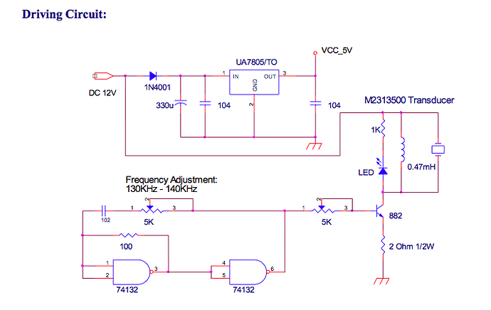
(1) The first thing I don't understand is why is there a VCC_5V being regulated but the driving circuit is powered directly by the DC12V instead? Where is this VSS_5V used?
It's not shown in the drawing, but the 74132 gate chip requires both a ground connection (pin 7) and a +5vdc (pin 14) connection. It's also assumed the the 12vdc power source negative terminal is connected to the ground connections shown on the drawing.
Are the two 74132 symbols the same physical component (considering the input/output numbering on the first and second symbol are different)?
At first, the fact that 1 & 2 inputs and 4 & 5 inputs were wired together seemed odd the 74132 NAND, but I guess it means that it will always generate a 1 when the inputs are 0 and 0 and will generate 0 when the inputs are 1 & 1. Is there a circuit simulator somewhere that could show how this circuit behaves?
retrolefty:
(2) The second thing is that I don't understand how the frequency is generated using the 74132/capacitor/resitors but I will take that as a homework (hints appreciated) and I will read up on it: possibly with more specific questions here later.
It's forms a simple R/C relaxation oscillator circuit. By using an adjustable pot for the R, the frequency can be varied in the range shown.
Why are there two 5K pot and how do I adjust the 130-140 range based them?
Does this also mean that once I am satisfied with a specific frequency, say 138Khz, I could substitute them for a fixed resistor? Or it is always better to use a pot since it could be hard to find an exact resistor for the give frequency?
I guess I should use a pot but find one that is not easy to change? Maybe one that requires a screw driver to adjust?
retrolefty:
(3) The third thing is that I was wondering if there are components/subsets I can trim out of this circuit since I will be using an arduino board to control it. Basically, are there overlapping functions that Arduino could take over? Can an arduino uno board generate these frequencies directly? I understand that the 5V will be provided by arduino and I won't need the voltage regulator, but not sure about the current: is arduino enough to drive this?
Yes, if you can develop a frequency in your sketch and have it toggle an output pin, then you can wire it to pin 1 of the right hand pot. You also need a common ground wire run from this circuit to a Arduino ground pin. Then you can eliminate the +5vdc regulator and it's supporting components and the 74132 chip and it's supporting components.
However the circuit seems pretty good and if you don't want to have the software overhead of generating the oscillator frequency, you could just build it as shown and modify it slightly to allow the Arduino to start and stop the pulse generation. To do this simple disconnect pin 2 from the 74132 and instead wire it directly to a Arduino output pin. Also you will still need to have a ground wire between this circuit and the arduino ground pin. Now when you make the output pin High the pizo will transmit the pulses, make it low and the pizo will be off.
Let me see if I get this right. If I disconnect pin 2 from the 74132 (NAND afaik) and connect it to an Arduino output pin, what could be only NOT(0 & 0)=1 or NOT(1 & 1)=0 can be any of the 4 cases (the previous two plus the NOT(0&1)=1 or the NOT(1&0)=1. If the Arduino output pin is off then the first NAND will generate either a 0 or a 1 depending on the voltage on 74132 pin 1, which means that the second NAND will generate a 0 or 1. Humm, does that mean that the Arduino out should be 1 to turn off and 0 to turn it on and that 74132 input pin 1 is always 1?
Would you say it would be more robust using this circuit as opposed to emulating this in software? And what about power consumption: would a Arduino implementation or this circuit be more power hungry?
For now, I'll stick to the circuit and may play around with Arduino as a learning experience.
retrolefty:
(4) A final thing is re: power. Since I am planning to use solar power in the future, what is the minimum power I can consume to generate these frequencies? Could this circuit be improved to reduce power consumption?
More then likely, however the pizo pulses themselves and the duty cycle you need to use, and the distance you need the ultrasonics to carry will set a floor on how little current such a circuit would consume. I would suggest sticking to the proven circuit for now, get your software working and then measure the current consumption for the whole system, arduino included before looking at where the best current saving opportunities lie.
PS: that LED in the circuit is shown wired backwards, so either reverse the leads if you want it, or remove it if you don't want the extra 10ma intermittent current consumption it will draw while transmitting pulses.
Lefty
This circuit is to drive a micro nozzle ultrasonic atomizing transducer (Resonant freq=135.0+-5KHz, Impedance=10 Ohm typ., capacitance=2450+-20%pF). It is a piezo transducer attached to a micro nozzle plate with micron sized oriffices. the nozzle plate will sit on the surface of a liquid container and atomize liquids. So I don't need to produce sound per se, nor the sounds needs to travel distances, and the nozzle plate makes this process more efficient than the MHz foggers you see being sold for decoration (or at least I hope so).
But, you point is: build the circuit, get this thing atomizing water and measure the power consumption. Once I know that I could see whether there is room for making this circuit less power hungry (if at all).
yuri

