david_prentice:
In real life. Which device to you go to first?
These days definitely the 400Msps logic analyzer.
I used it a lot on 3 week vacation that started mid August, and two hospital stays since then.
I always have a WoodenBoardPi, some other PIs with HQ cameras, 5000lm diy highspeed flash and logic analyzer, and some Arduinos with me
Your 400Msps link does not point to a specific device.
The link to the product I bought 2016 is dead.
And my device has a different connector, this seems to be the same device as I own: https://www.aliexpress.com/item/4000920413699.html
I always have to connect the big connector with all channel cables.
The new product has several connector cables, so you can connect less channels if you need less.
16MP photo with my connector:
P.S:
Currently I use the 400Msps analyzer for completely getting one or two cores from Raspberry Pi out of Linux control. The exported captured 400Msps data for core2 revealed that still something happens on core2, mainly the big delays are 100Hz frequency timer interrupt I am trying to get rid of on core2 to have it 100%, similar to a microcontroller (while Raspberry Pi OS happily runs on the other cores): https://www.raspberrypi.org/forums/viewtopic.php?f=72&t=245561&start=25#p1750115
Sorry, no axis labelling in this diagram (Y-axis is nanoseconds, X-axis measurement number), Mark_T warned me on that in the past. But the 1.6 million lines of exported data CSV file got truncated on import, LibreOffice calc can only deal with 1 million rows, and with that many rows even a 32GB ram PC allows for only very sloooow working:
HermannSW:
Sorry, no axis labelling in this diagram (Y-axis is nanoseconds, X-axis measurement number), Mark_T warned me on that in the past. But the 1.6 million lines of exported data CSV file got truncated on import, LibreOffice calc can only deal with 1 million rows, and with that many rows even a 32GB ram PC allows for only very sloooow working:
Today I was not able to get any diagram with more than 1million rows out of LibreOffice.
I learned that gnuplot does not have any problems with 1million rows.
So just changing comma with space to go to gnuplot data input format.
Drawing 1million rows data file took <1min, need to figure out how to set axis titles.
Start gnuplot, and then do "plot data.dat" on gnuplot command prompt(Y-axis is delta time in seconds): https://www.raspberrypi.org/forums/viewtopic.php?f=72&t=245561&p=1751854#p1751854
I have lost the plot somewhere. This thread was about comparing digitalWrite() versus direct port access.
You appear to have captured millions of pulses and logged the execution times.
So there will be several 1ms Timer interrupts
And several USB interrupts.
Obviously the ISR()s might fire part way through the pulse. And consequently the interrupted pulses will take longer.
I wrote some generic macros. Captured them with a Logic Analyser. Could make a serious estimate of the number of machine cycles.
I could have specifically triggered on a Timer or USB interrupt. But I don't see the point.
I found it interesting that a SAM3X M3 from Atmel was the same as the F103 M3 from ST. These are both "elderly" chips that appeared about the same time i.e. 15 years ago.
More interesting was the difference between the SAMD21 M0 versus the F072 M0 from ST.
However there is a "fast access trick" that you can use on the SAMD21 which puts the Atmel in the same cycles as ST.
Write-Only is dramatic on all ARM chips.
However the Port-Access version can be used on any Arduino. And gives a pretty good performance e.g. when used in classes that allow "digital pin" arguments at runtime.
In my personal opinion, classes should use compile-time pin mapping if speed is important.
After all, you know how you are going to wire your display etc at compile-time.
The difference between the first and 2nd diagram is, that timer interrupts on Pi2B core1 were completely turned off, and that program blink.c toggling GPIO17 was the only code running on core1 (by taskset command). So something still leads to longer than 105/2ns time deltas.
I expected a perfect plot of the 1,353,042 rows exported by 400Msps logic analyzer, but got still (very few) 1.4us time deltas I would not expect to see on a microcontroller:
For details on small Due sketch used and the square wave generated see the pointed to posting.
Currently I suspect that the 400Msps logic analyzer itself can be responsible for the few 1.4us time deltas shown for data captured on Due pin D53 ...
The logic analyzer is not responsible for the 1.4us time deltas, as can be seen by below very clean 4.8million row gnuplot of 105ns period Pi2B 50% duty pwm signal capture on a different pin.
What can it be, that introduces 1.4us time deltas on a Raspberry Pi2B and on Arduino Due?
I want to get rid of the 1.4us delta times on the Due hoping that identifies what else I need to disable on Raspberry Pi2B to make a single core not under linux control more microcontoller like.
I was successful in identifying the cause of the 1.4us delta times.
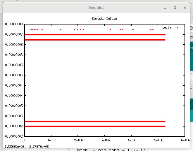
It generates a square wave with period 95ns, 25ns high, 70ns low.
gnuplot diagram of more than 5.2million rows data shows bars around 25ns, 70ns and 1.1µs:
Then I added just "noInterrupts()" after the pinMode command, that was all that was needed.
Now a perfect plot, 25ns and 27.5ns are apart 2.5ns, the resolution of my 400Msps logic analyzer.
Same is true for 67.5ns/70ns/72.5ns -- I wish there would be similar "noInterrupts()" call for the Pi2B (at least for a core not under Linux control).
S
I deliberately run 100 edges so that I have a substantial sequence to measure with my Logic Analyser.
The sample speed is not critical. I can detect all 100 edges from the slower MCUs. I know that the individual pulses on M3 and M4 might not be measurable.
I capture a GPIO pin that marks begin and end of the sequence.
All that matters is 2 cycles @ 84MHz is 23.8ns to execute a SODR instruction.
Interrupt latency and service is irrelevant. Likewise whatever machine instruction is used for the goto.
It should be a lot faster than the existing digitalWrite() for due, depending on exactly how it gets used.
A problem is that the ARM chips just don't benefit from constant value operands as much as the AVR - the AVR has special instruction for constant bit set/clear, but the ARM...
The above code is a good example. It only makes SLIGHT use of the fact that the Pin is a constant. In a tight while loop it compiles to:
  while (1) {
    digitalWriteFast(PIN, 0);
    digitalWriteFast(PIN, 1);
  }
   80150:       4a03            ldr     r2, [pc, #12]   ; get gAPinDescription
   80152:       f8d2 316c       ldr.w   r3, [r2, #364]  ; get port
   80156:       f8d2 2170       ldr.w   r2, [r2, #368]  ; get bit
loop:
   8015a:       635a            str     r2, [r3, #52]   ; store bit in CODR register.
   8015c:       631a            str     r2, [r3, #48]   ; store bit in SODR
   8015e:       e7fc            b.n     8015a <do_writes()+0xa> (jump loop)
Note that the second use gets HIGHLY optimized (since it already has the port and bit), and the loop itself is very tight (just the two stores and a jump.)