Hi everybody,
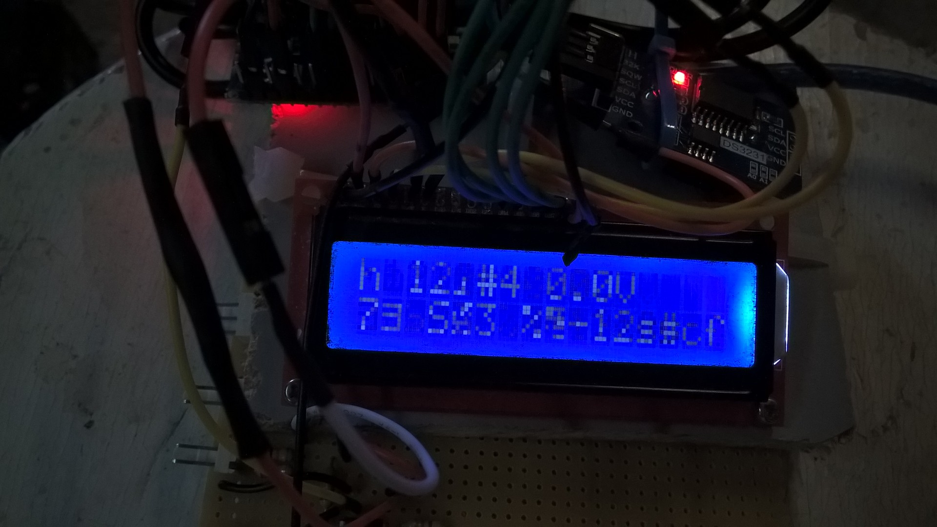
I'm building a bike Dashboard with a LCD displaying several parameters. Today I ran a test but it seems the arduino is getting mad near the engine. As I place it at ~40cm next to the ignition, my RPM is caught as it should. But when it's closer, even the speed returns a value (the input is not wired yet). Everything in my display starts scrolling, blinking, showing weird characters (see the image).
It is a prototype so wires are large and running around the board (maybe a part of the problem ?).
Is it due to an extreme sensivity of the arduino board ?
I wanted to use a plastic housing but an aluminum one would be better for electromagnetic shielding ?
Help me !
Hi,
I think that is why ECU and other electronics in motor vehicles are inside the cabin with a metal firewall between them.
Is your arduino in a fully closed metal box and have you bypassed the power supply with bypass capacitors.
Ignition is high energy electrical pulses, it can get induced into any nearby wire or even the earth of the car.
Tom..... ![]()
The placement of wires to and from the motor for the dashboard should be kept away from other high voltage sources.
As I said, I'm at the prototype step so my board is completely nude... I will try a metal box.
TomGeorge:
have you bypassed the power supply with bypass capacitors.
What do you mean ?
In the internet I can only find high frequency shielding docs but nothing suitable for ignition.
And you must keep all the wiring bundled closely together. No loops.
Hi,
What is this connected to that the arduino is close to the ignition circuitry.
Bypassing is when you place 0.1uF capacitors across any power wires to bypass any noise that may be induced in them.
In your case t the Battery + and gnd.
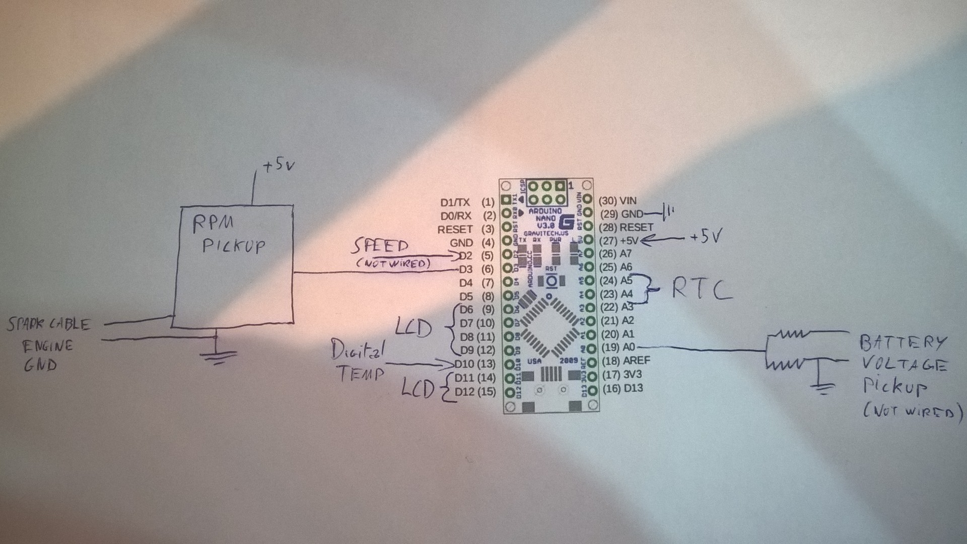
Can you please post a copy of your circuit, in CAD or a picture of a hand drawn circuit in jpg, png or pdf?
Thanks .. Tom.... ![]()
The board is connected to a mobile power bank not the bike battery.
Should I add filtering capacitor to the rpm pickup circuit ?

Ignition leads produce far more interference than is allowed from, say, a piece of domestic
electrical or electronic equipment. Orders of magnitude more since the voltage is ~ 20kV and
ignition leads are/were not normally screened (I have no idea why - you can get screened leads though).
MarkT:
ignition leads are/ were not normally screened
Except of course, in aircraft - where it matters.
MarkT:
I have no idea why - you can get screened leads though.
Two reasons, most likely:
-
Historically - there wasn't any sensitive electronics in the engine compartment, so no need to screen anything.
-
Profits - adding such screening would increase the cost of the car, or decrease the profits; in the first case, the consumer wouldn't see any direct benefit, and in the second case - well, who in their right mind would want to lose money if they didn't have to?
Likely, the current solutions to the problem are cheaper (and maybe more effective?) than adding extra screening, etc - to the wires. Also - there's the move toward coil-on-plug, which should also decrease some of the noise because while there's more coils, the amount of voltage and current can likely be less because the HV leads are closer to the sparkgap (and they are easier and cheaper to shield with such a design I would imagine).
At least - those are my guesses as to "why"...
![]()
Hi,
The board is connected to a mobile power bank not the bike battery.
Have you got the gnd of the bike battery connected to the gnd of the arduino circuit?
Tom..... ![]()
TomGeorge:
Hi,
Have you got the gnd of the bike battery connected to the gnd of the arduino circuit?Tom.....
I tried but it amplifies the parasites...
Non-resistor spark plugs emit more noise. Doublecheck that your plug has a resistor either by looking up the part number or using your multimeter (should be ~4K ohms).
inryjo:
I tried but it amplifies the parasites...
Need Lyclear.
Paul__B:
Need Lyclear.
Sorry, English in sot my mother tongue, interference was the appropriate word... ![]()
Have a few ferrite cores handy?
For your RPM signal, try using a series 1K resistor ... if not resolved, try adding a ferrite core (wrap this wire through it 1-turn (straight through) then test. If not resolved, try 2 turns, and so on up to 10 turns.
Make sure its not too many turns as this could limit the maximum RPM or pulse rate that can be monitored.
I'm sure you'll need to connect the grounds ... could use a ferrite in this GND to GND wire with 5-10 turns through a ferrite core (the more turns the better). The +5V supply wire could also be wrapped through this core (5-10 turns if possible).
EDIT: I'm assuming the RPM pickup signal is in the 0-5V range. If not, an appropriate voltage divider is needed, or higher value series resistor to limit the input's internal protection diode current to <=1mA.
dlloyd:
Have a few ferrite cores handy?For your RPM signal, try using a series 1K resistor ... if not resolved, try adding a ferrite core (wrap this wire through it 1-turn (straight through) then test. If not resolved, try 2 turns, and so on up to 10 turns.
Make sure its not too many turns as this could limit the maximum RPM or pulse rate that can be monitored.I'm sure you'll need to connect the grounds ... could use a ferrite in this GND to GND wire with 5-10 turns through a ferrite core (the more turns the better). The +5V supply wire could also be wrapped through this core (5-10 turns if possible).
EDIT: I'm assuming the RPM pickup signal is in the 0-5V range. If not, an appropriate voltage divider is needed, or higher value series resistor to limit the input's internal protection diode current to <=1mA.
Yes it is 5v.
Thanks a lot for your advice, I'll try soon.
dlloyd:
Have a few ferrite cores handy?For your RPM signal, try using a series 1K resistor ... if not resolved, try adding a ferrite core (wrap this wire through it 1-turn (straight through) then test. If not resolved, try 2 turns, and so on up to 10 turns.
Make sure its not too many turns as this could limit the maximum RPM or pulse rate that can be monitored.I'm sure you'll need to connect the grounds ... could use a ferrite in this GND to GND wire with 5-10 turns through a ferrite core (the more turns the better). The +5V supply wire could also be wrapped through this core (5-10 turns if possible).
EDIT: I'm assuming the RPM pickup signal is in the 0-5V range. If not, an appropriate voltage divider is needed, or higher value series resistor to limit the input's internal protection diode current to <=1mA.
What about the size of those ferrite cores ?
I've got scrap coils (attached image). Can I use something either by decoiling it or serial add in my pickup/supply/gnd lines ? (I don't know the specs)
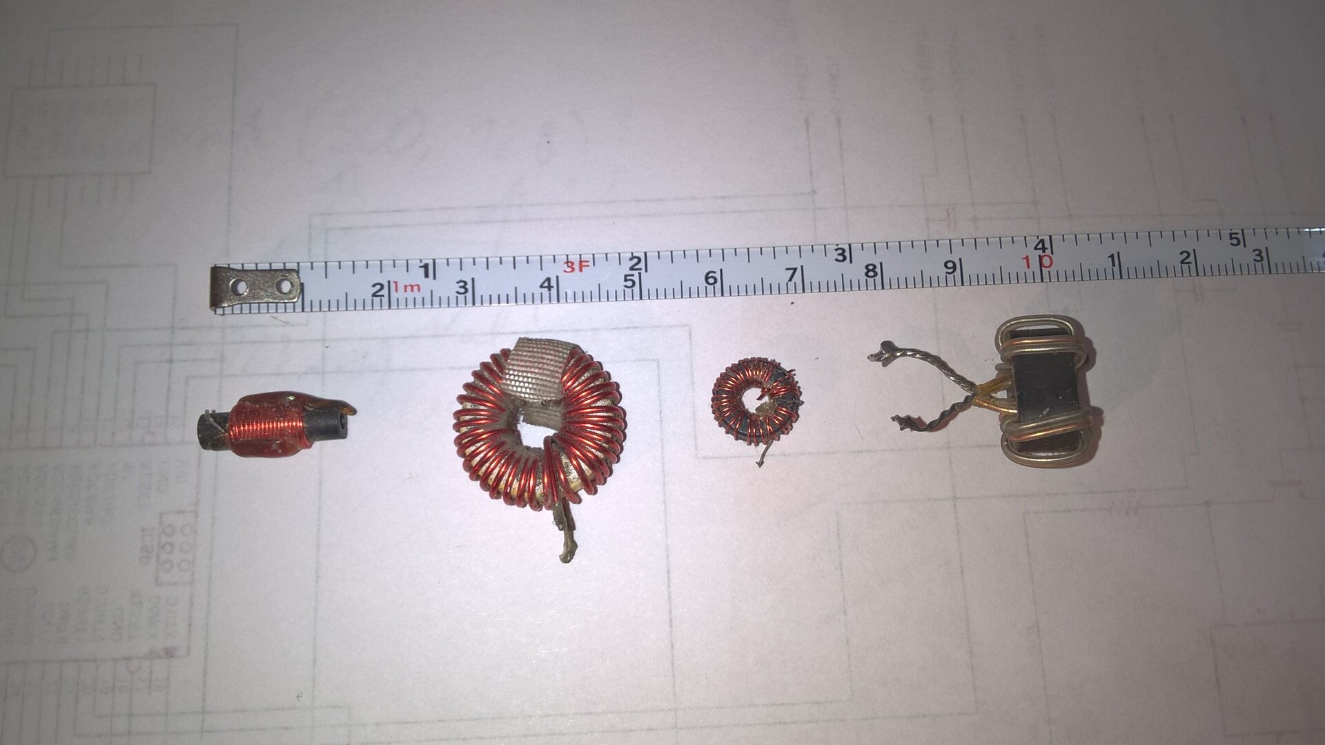
I would try the largest of the 3 right hand coils in the image.
EDIT: The second and last (left to right) look good. You could serial add them. Trial and error ... see which coils work best.
inryjo,
Was there any solution that worked for you?
I have the same problem with Mega going crazy near sparks system.
Please advice...