Just connected up my Arduino Mega to my tester board which uses an ATMEGA328P, pins are all setup correctly, having googled where the SPI pins on the mega are and attached to the respective pins on the tester board and yet I'm getting the following error:
Arduino: 1.8.12 (Windows 10), Board: "Arduino Nano, ATmega328P"
avrdude: Version 6.3-20190619
Copyright (c) 2000-2005 Brian Dean, http://www.bdmicro.com/
Copyright (c) 2007-2014 Joerg Wunsch
System wide configuration file is "B:\Program Files (x86)\Arduino\hardware\tools\avr/etc/avrdude.conf"
Using Port : COM3
Using Programmer : stk500v1
Overriding Baud Rate : 19200
AVR Part : ATmega328P
Chip Erase delay : 9000 us
PAGEL : PD7
BS2 : PC2
RESET disposition : dedicated
RETRY pulse : SCK
serial program mode : yes
parallel program mode : yes
Timeout : 200
StabDelay : 100
CmdexeDelay : 25
SyncLoops : 32
ByteDelay : 0
PollIndex : 3
PollValue : 0x53
Memory Detail :
Block Poll Page Polled
Memory Type Mode Delay Size Indx Paged Size Size #Pages MinW MaxW ReadBack
eeprom 65 20 4 0 no 1024 4 0 3600 3600 0xff 0xff
flash 65 6 128 0 yes 32768 128 256 4500 4500 0xff 0xff
lfuse 0 0 0 0 no 1 0 0 4500 4500 0x00 0x00
hfuse 0 0 0 0 no 1 0 0 4500 4500 0x00 0x00
efuse 0 0 0 0 no 1 0 0 4500 4500 0x00 0x00
lock 0 0 0 0 no 1 0 0 4500 4500 0x00 0x00
calibration 0 0 0 0 no 1 0 0 0 0 0x00 0x00
signature 0 0 0 0 no 3 0 0 0 0 0x00 0x00
Programmer Type : STK500
Description : Atmel STK500 Version 1.x firmware
Hardware Version: 2
Firmware Version: 1.18
Topcard : Unknown
Vtarget : 0.0 V
Varef : 0.0 V
Oscillator : Off
SCK period : 0.1 us
avrdude: AVR device initialized and ready to accept instructions
Reading | ################################################## | 100% 0.02s
avrdude: Device signature = 0x000000 (retrying)
Reading | ################################################## | 100% 0.02s
avrdude: Device signature = 0x000000 (retrying)
Reading | ################################################## | 100% 0.02s
avrdude: Device signature = 0x000000
avrdude: Yikes! Invalid device signature.
Double check connections and try again, or use -F to override
this check.
An error occurred while uploading the sketch
avrdude done. Thank you.
Was wondering what I'm missing here?
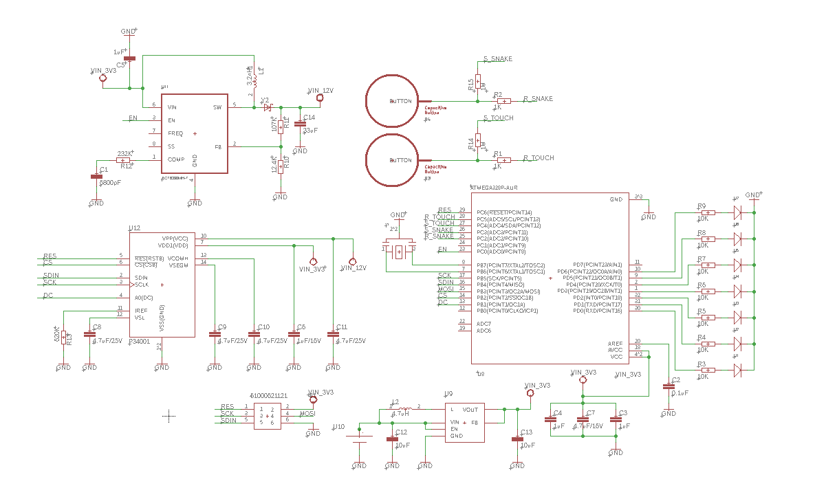
For those interested in the schematic please see below.
First of all, schematics you have posted is useless. Totally unreadable.
Depending on ArduinoISP sketch version the slave reset pin is 10 or 53 on Mega. You can take MOSI, MISO, SCK, 5V, GND from ISP 6pin header.
For ISP programming, the MCU needs:
- power
- clock
- reset
and of course ISP connection.
I can't see reset circuit on this blurry picture but maybe I am wrong.
Budvar10:
First of all, schematics you have posted is useless. Totally unreadable.
Depending on ArduinoISP sketch version the slave reset pin is 10 or 53 on Mega. You can take MOSI, MISO, SCK, 5V, GND from ISP 6pin header.
For ISP programming, the MCU needs:
- power
- clock
- reset
and of course ISP connection.
I can't see reset circuit on this blurry picture but maybe I am wrong.
Schematic isn't useless, Inserting the image from Gyazo formatted it to the size you see in the post, for the full size - Just right click the image & select "Open image in new tab"
The tester board already has clock and reset, power is coming directly from the mega's 3.3V line into the ISP 6 pin header on the tester board.
I did wonder about the pin 10 on the mega, I had used pin 10 in the past but tried it with Pin 53 to see if any different and seems to not work, so I'll revert back to pin 10 and see what happens.
I didn't think you could use the 6 pin ISCP header on the mega as that was for if I was programming the mega from an a different board.
Schematic isn't useless, Inserting the image from Gyazo formatted it to the size you see in the post, for the full size - Just right click the image & select "Open image in new tab"
Great, it works.
I didn't think you could use the 6 pin ISCP header on the mega as that was for if I was programming the mega from an a different board.
You can. They are identical, see the schematics.
The tester board already has clock and reset, power is coming directly from the mega's 3.3V line into the ISP 6 pin header on the tester board.
I did wonder about the pin 10 on the mega, I had used pin 10 in the past but tried it with Pin 53 to see if any different and seems to not work, so I'll revert back to pin 10 and see what happens.
You cannot use 3.3V power for programming. Mega has 5V so it destroyed the chip without voltage level transceiver.
I do not see RESET pulled up. I don't know P34001 and cannot find it on web so not sure about RESET. ATmega must have RESET on HI to start. Anyway, I am recommending to add whole reset circuit like from Arduino UNO/Mega.
Budvar10:
You cannot use 3.3V power for programming. Mega has 5V so it destroyed the chip without voltage level transceiver.
Have used the same 3.3V on a previous version of the test board using 3.3V using the same circuit so I know it works, only different with this circuit is I added some extra resistors to the capacitive sensors as I forgot to add receive and send pin, rather just had a send pin.
Budvar10:
I do not see RESET pulled up. I don't know P34001 and cannot find it on web so not sure about RESET. ATmega must have RESET on HI to start. Anyway, I am recommending to add whole reset circuit like from Arduino UNO/Mega.
You can ignore P34001 its a 256x64 OLED display, done by a chinese supplier, unless you have the datasheet from the manufacturer there won't be any information out there on it.
Treat it like the OLED displays from Adafruit.
Your '328P schematic has Reset & MISO swapped from the standard arrangement.
Can the chips at the left handle 5V? If they can, I would leave the 12V off, and power what's left from the Mega 5V.
I would also recommend 10K Reset pullup resistor to Vcc.
Are C3 or C4 0.1uF? They look like 1uF.
0.1uF would work better there with decoupling of noise back onto the 3.3V line as the chip switches internally.
CrossRoads:
Your '328P schematic has Reset & MISO swapped from the standard arrangement.
Can the chips at the left handle 5V? If they can, I would leave the 12V off, and power what's left from the Mega 5V.
I would also recommend 10K Reset pullup resistor to Vcc.
Are C3 or C4 0.1uF? They look like 1uF.
0.1uF would work better there with decoupling of noise back onto the 3.3V line as the chip switches internally.
I'll try swapping the pins around just in case, although not sure that's the case as Pin 29 is RESET & Pin 16 (SDIN) is the Miso.
Chips on the left hand side can't handle 5V, this is following the manufacturer's recommendation in their datasheet.
C3 & C4 are 1uF, I think if I remember correctly as I did schematic a long time ago, this based off a Arduino Nano setup, and those were the capacitors used for the Nano schematic. Again could be wrong but was a long time ago, that I did the original schematic, only updated the capacitive sensor section a month or so ago.
I'm not too fussed over the noise personally as once the board code is done it'll just be preprogrammed without the need of the ISCP header.
InsertTitle:
I'll try swapping the pins around just in case, although not sure that's the case as Pin 29 is RESET & Pin 16 (SDIN) is the Miso.
Just swapped the wires over on the prototype board's ISCP header exactly the same result
minus 1 change.
Avrdude: Device signature = 0xffffff (probably.avr8x_mega) (retrying) showed instead of just saying retrying.
Edit: Not too sure if this matters or not but I'm uploading the sketch to the board without a bootloader installed, as I have no need for one.
Avrdude: Device signature = 0xffffff (probably.avr8x_mega) (retrying) showed instead of just saying retrying.
Shortage on some bus wire.
Edit: Not too sure if this matters or not but I'm uploading the sketch to the board without a bootloader installed, as I have no need for one.
It doesn't matter, uploading process is the same.