Arduino joystick to PPM

Hi all

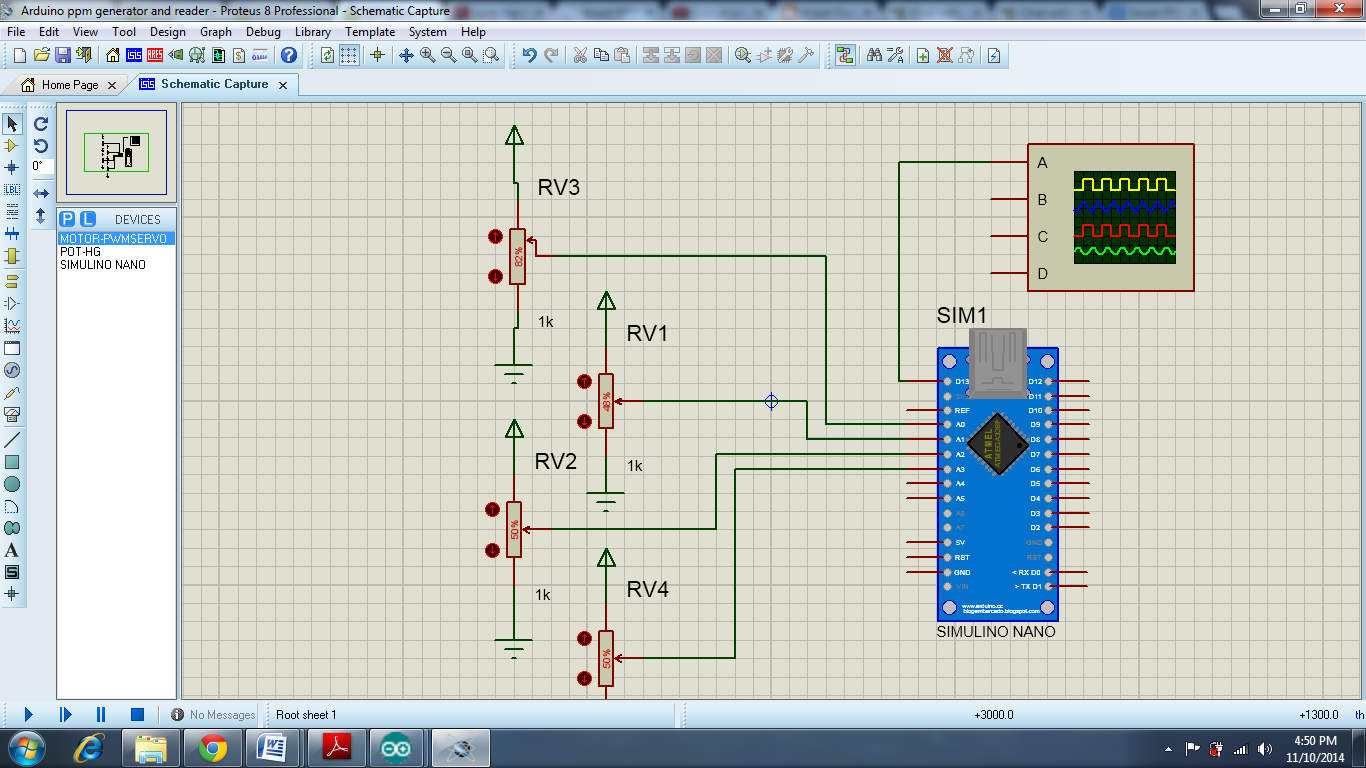
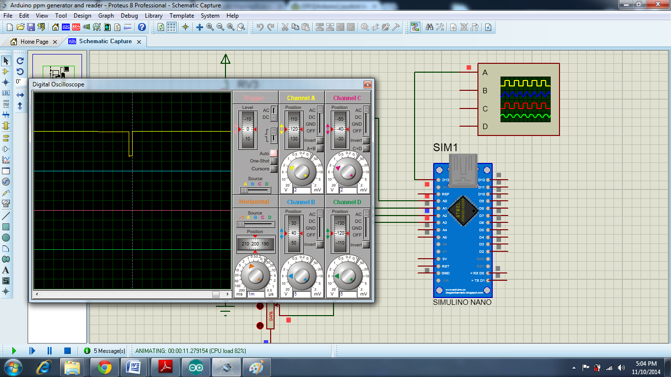
I tried to simulate in Proteus code below but it does not work, can someone help me?

#define NB_WAY 6 // number of ways
#define LOW_LENGTH 300 // How long last (in µs) a low between 2 pulses
#define MIN_PPM_PULSE 1300 // minimum pulse length in µs
#define PPM_PULSE_LENGTH 700 // how much more µs will last the max pulse length
#define PACKET_LENGTH 21000 // How long (µs) last a full trame

// trame length is fixed ! Every trame will make PACKET_LENGTH µs !
// MUST NO BE MORE THAN 32ms !!! (timer's prescaler constraint)

#define PPM_OUTPUT 13 // OUTPUT PIN

int way_value[NB_WAY];
int way_pin[NB_WAY];
int way_min[NB_WAY];
int way_max[NB_WAY];

int i = 0;
int p = 0; // temp var for duty cycle calculation
int last_i_timer = 0; // last way's value sent through PPM signal
unsigned long int trame_elapsed_time = 0;
bool output_state = LOW;

void setup() {
  // ppm output :
  pinMode(PPM_OUTPUT, OUTPUT);
  digitalWrite(PPM_OUTPUT, output_state);
  
  // inits arrays
  for(i=0;i<NB_WAY;i++)
  {
    way_pin[i] = 14 + i;
    pinMode(way_pin[i], INPUT);
    way_value[i] = analogRead(way_pin[i]);
    way_min[i] = way_value[i];
    way_max[i] = way_value[i];
  }

  // init timer
  cli();          // desactivation interruptions
  TCCR1A = 0x00;  // set timer1 registers to 0
  TCCR1B = 0x00;     
  TIMSK1 = 0x00;
    
  OCR1A = 65535;// set to the max
    // CTC mode:
  TCCR1B |= (1 << WGM12);
    // prescaler to 8, that allow (@16mhz) 32.8ms trame
  TCCR1B |= (0 << CS10);
  TCCR1B |= (1 << CS11);
  TCCR1B |= (0 << CS12);
    // timer activation
  TIMSK1 |= (1 << OCIE1A);
  sei();
}

ISR(TIMER1_COMPA_vect)
{
  TIMSK1 &= (0 << OCIE1A);
  if(output_state)
  { // END OF A HIGH, we have to wait LOW_LENGTH ms before next pulse 
    output_state = LOW;
    digitalWrite(PPM_OUTPUT, output_state);
    OCR1A = 2 * LOW_LENGTH; // set when next timer interruption will occur
    TIMSK1 |= (1 << OCIE1A);  // restart timer
    trame_elapsed_time += LOW_LENGTH;
  }
  else
  { // END of a LOW_LENGTH, new pulse !
    output_state = HIGH;
    digitalWrite(PPM_OUTPUT, output_state);
    if(last_i_timer >= NB_WAY) // last way, so wait until next packet
    {
      OCR1A = (2 * PACKET_LENGTH) - (trame_elapsed_time * 2);// set when next timer interruption will occur
      TIMSK1 |= (1 << OCIE1A); // restart timer
      last_i_timer = 0;
      trame_elapsed_time = 0; 
    }
    else
    {
      OCR1A = 2 * way_value[last_i_timer];// set when next timer interruption will occur
      TIMSK1 |= (1 << OCIE1A); // restart timer
      last_i_timer ++;
      trame_elapsed_time += way_value[NB_WAY];
    }
  }  
}


void loop() {

  for(i=0;i<NB_WAY;i++)
  {
     // Read current value of way i :
     p = analogRead(way_pin[i]);
     
     // auto calibration...
     if(p > way_max[i]) way_max[i] = p;
     if(p < way_min[i]) way_min[i] = p;
     
     // Arduino map function sucks
      way_value[i] = MIN_PPM_PULSE + PPM_PULSE_LENGTH * (float)((float)(p - way_min[i]) / (float)(way_max[i] - way_min[i]));
  }
}

Moderator edit: CODE TAGS

but it does not work

Grrrr.

Maybe the compiler objects to the italics.

USE CODE TAGS

It compiles without errors, but does not work ...

OK, let me put it this way.

USE CODE TAGS.

Tell us what "it doesn't work" means.

What are actually trying to do?
What is all the Timer stuff for?
Can't you just use Servo.write()

...R

This code is for 4 ch ppm encoder, should look like.....should look like, or I'm wrong

Well, yes, you are wrong.

Your code is illegible (I've hinted at this already) and you haven't told us what "does not work" means.

We could ping-pong like this for some time, but I'll probably get bored.

not generate pulse ppm tre for 4 ch ... from what I referred

Would you please explain me what does not, I am new to arduino programming, please excuse me if I have done something wrong...

OK, I've fixed one of your problems.
Now, you've told us what it doesn't do - how about explaining what it does do?

I want to build a remote control 4 ch ppm, the code does not generate 4 ch, what this is about.
I want to know why does not work, what is wrong in the code?

evan230:
This code is for 4 ch ppm encoder, should look like.....should look like, or I'm wrong

Why do need a 4 ch ppm encoder?

What is going to use the data that the Arduino produces?
Or, to say it a different way, what will be connected to the Arduino?

...R

I want to know why does not work

You have the hardware in front of you.
We don't.

It does something.
It may not do what you want, but you need to explain to us what it actually does do.

I want to build a RC TX/RX with 433Mhz rf module for 4 ch.

evan230:
I want to build a RC TX/RX with 433Mhz rf module for 4 ch.

It's OK, you don't have to ask permission.

evan230:
I want to build a RC TX/RX with 433Mhz rf module for 4 ch.

It had crossed my mind that this is what is in your mind.

Could you please answer the questions in my earlier Reply 10 ?

And another question - what is the Tx/Rx going to control, and how will the control signals get to that device?

If you insist on keeping everything secret I am not going to waste time asking questions.

...R

I want to build a RC TX/RX with 433Mhz rf module for 4 ch.

Do you understand that the typical RC receiver acts somewhat like a shift register for the pulses sent by the transmitter? The below has some images depicting this method of operation.

https://www.google.com/search?q=rc+ppm+signals&num=100&lr=&as_qdr=all&tbm=isch&tbo=u&source=univ&sa=X&ei=eqtmVJCiEsqZNpWJgTA&ved=0CB8QsAQ&biw=1049&bih=627#imgdii=_