Hi guys, soo let me start off with being honest I don't have much expierence w with this.
I have bought a couple arduino clones 1 uwb c from ali and 2 from a thrusted seller that I have previously bought from. Installed the ch340 drivers restarted oc and got to work.
I am making a spiderman halloween outfit with those shrinking eyes. And I am running 2 Servo and 2 ir diodes.
As I was done soldering I put it in my pc and my first one exploded in my face and the second started burning before I pulled it out the wiring is as follows.
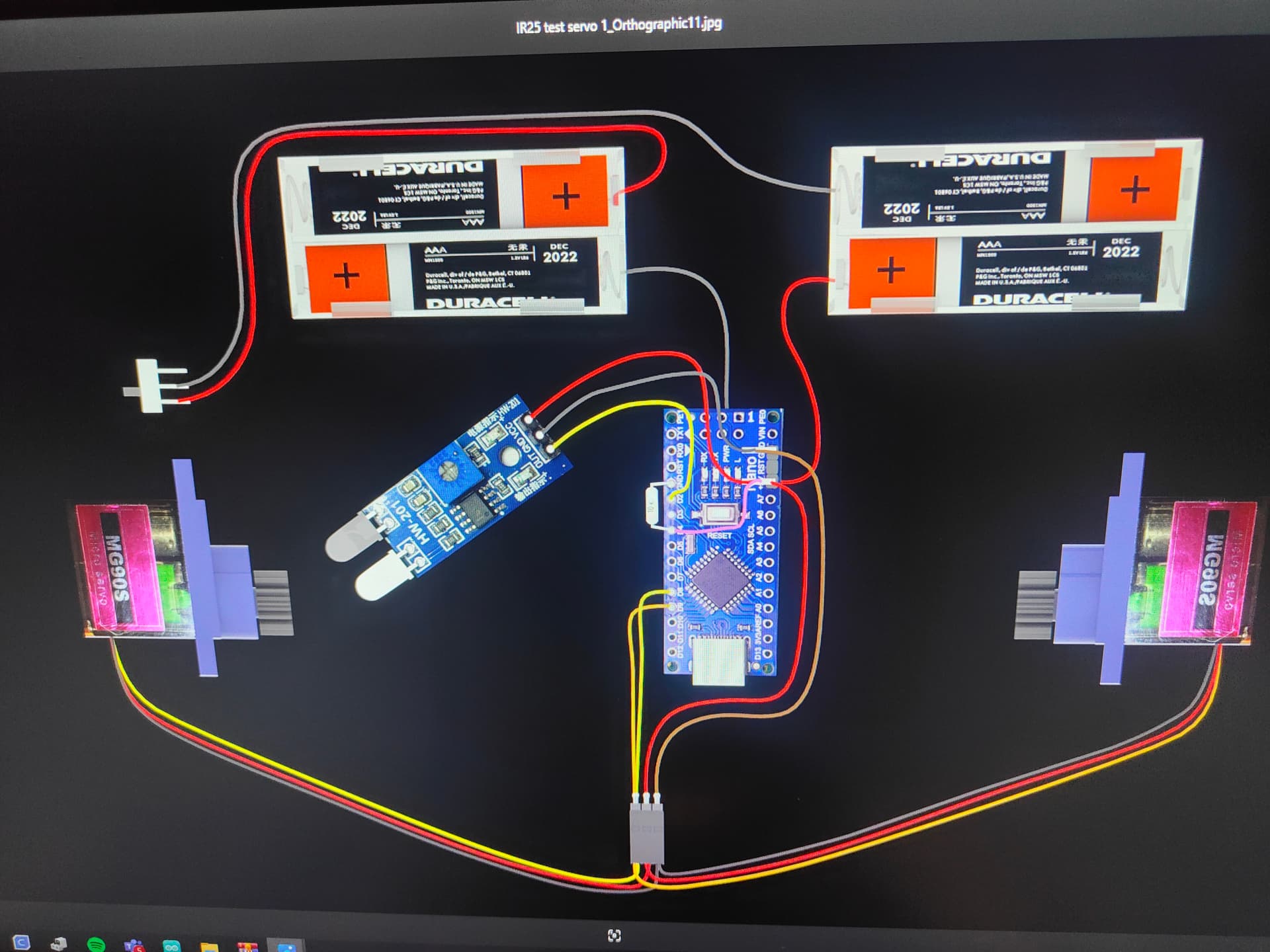
10k resistor between gnd and d4
5v has 3 output of which 2 are servo cables but no servo connected. And a ir sensor.
Gnd has those same ones
Output wire from d2 to ir sensor
D8 and d9 control servo.
I have checked for any shorts but couldn't find any
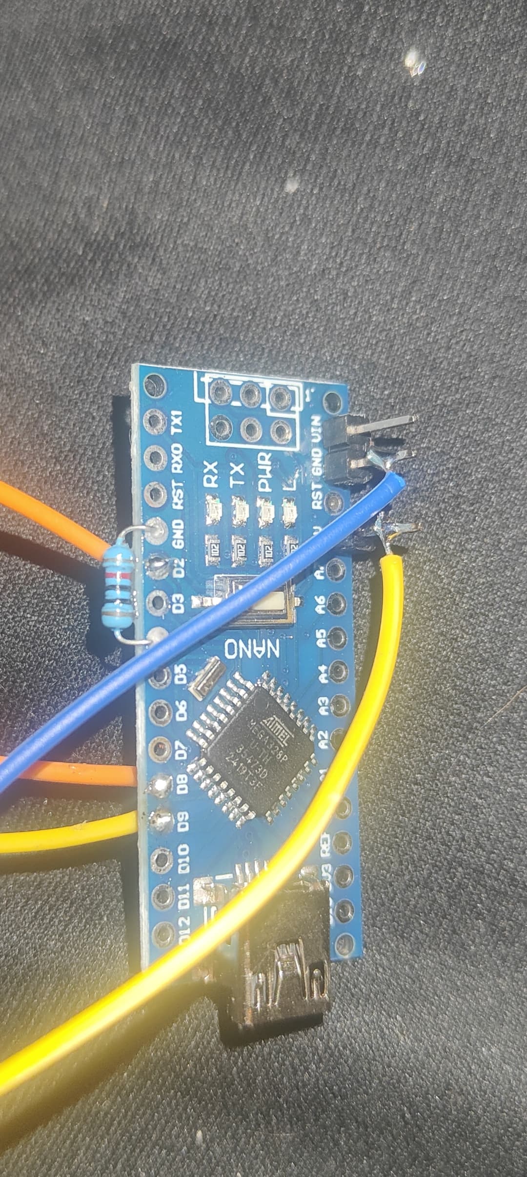
Soo here is what I have done and what it should look like. Only difference is I have not installed the battery pack yet, and I have tried the d4-5v and without it(real pic is without)
I mean for the usb c version that blew up is aliexpress https://a.aliexpress.com/_EzJqPR2
And the new ones are bought from a dutch seller. That have many electronics like raspberry where I have bought from many times. The servo i didn't connect yet as I didn't want it to draw to much power already so it is just the cable for now
Alright I will admit I am not used to soldering small electronics as I am used to car and motorcycle wiring🤣 also I didn't install the battery pack yet. But could you help me clean it up a bit to where it will work?
Well I am not sure how yet but if somehow I can directly mount the servo to the power supply? And the 2 ir sensors to the arduino? Would that be viable?
Or maybe use a different type of board like a stm32 or even a pi zero?
Just connect externally both servos (+/-), battery and two wires going to arduino (VIN and GND) so you don't have to deal with multiple wires when soldering to arduino board.
Arduino doesn't explode if you feed 6V to 5V pin (but will get damaged), so you probably made short circuit with your "artistic " soldering.
Even more delicate boards, for sure doesn't solve your problems.
Sorry mate for the soldering like I said I am not used to wire such small and delicate wires🤣
But that sounds like a good idea. Will let you know if it works, can I use the same code tho?
Before I forget can I power 2 of those IR sensors(hw-201) using the arduino? Or should I also power it from the external power supply?
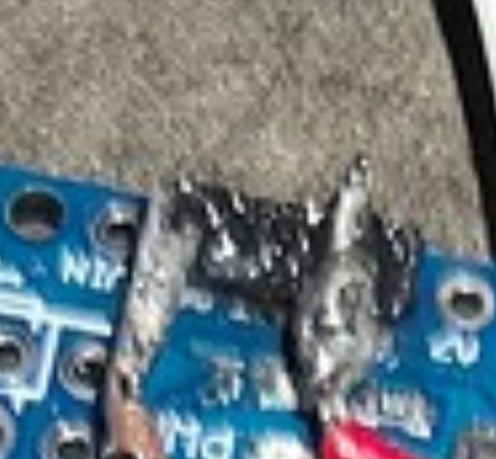
Soo this is the update: I did it like you said(left vin for a bit later but did solder a joint to, rerouted the steppers to paralel, yet it still overheated I did manage to find a better soldering iron soo it does look a little bit better, and I could localize the problem more, the gray "dust" on it was not there when I finished soldering, it was only after the pcb got quite hot and disconnected from my pc
Difficult to follow your description, feel free to post a wiring scheme.
Make sure you don't have any solder bridge/gray dust before you power up the board.
Sorry mate! The gray dust occurred after I turned on the board I unfortunately didn't take pictures before turning it on, but I visually inspected it. Also for any bridges but nothing, it looked clean. I will make an updated schematic in a few mins.
As for what I describe as gray dust: after soldering I checked all the solder points and they looked clean, I went to plug it in and after rougly 2 mins it started burning and the gray dust appeared
Small update: after cleaning with a little bit of iso alcohol it did fully go away again