cattledog:
The 7815 value came from your post #15 when you switched to 1 Hz for simplicity and I carried on using it.
Use whatever values give the best result on the scope. The processor clock is not highly accurate and if you need very specific periods it is best to set it experimentally for the processor used.
I still believe that you issues with "inversion" and the need for the unusual procedure used to create the leading LOW is related to your use of fast pwm to OCR4A with a toggle on compare match.
You may be better off using fast pwm to ICR4 which allows you to set an inverting mode at a compare match halfway to the ICR4 top value. Using the compare match at OCR4A TOP with a toggle at 2X the frequency is creating issues.
Furthermore, since you are trying to control the direction change of a stepper at 2Hz, there I'm not sure I see the need for a hardware timer. With a software timer using millis or micros you might have more control over the pattern.
Hi cattledog, many thanks for your prompt reply. Always appreciate your advices.
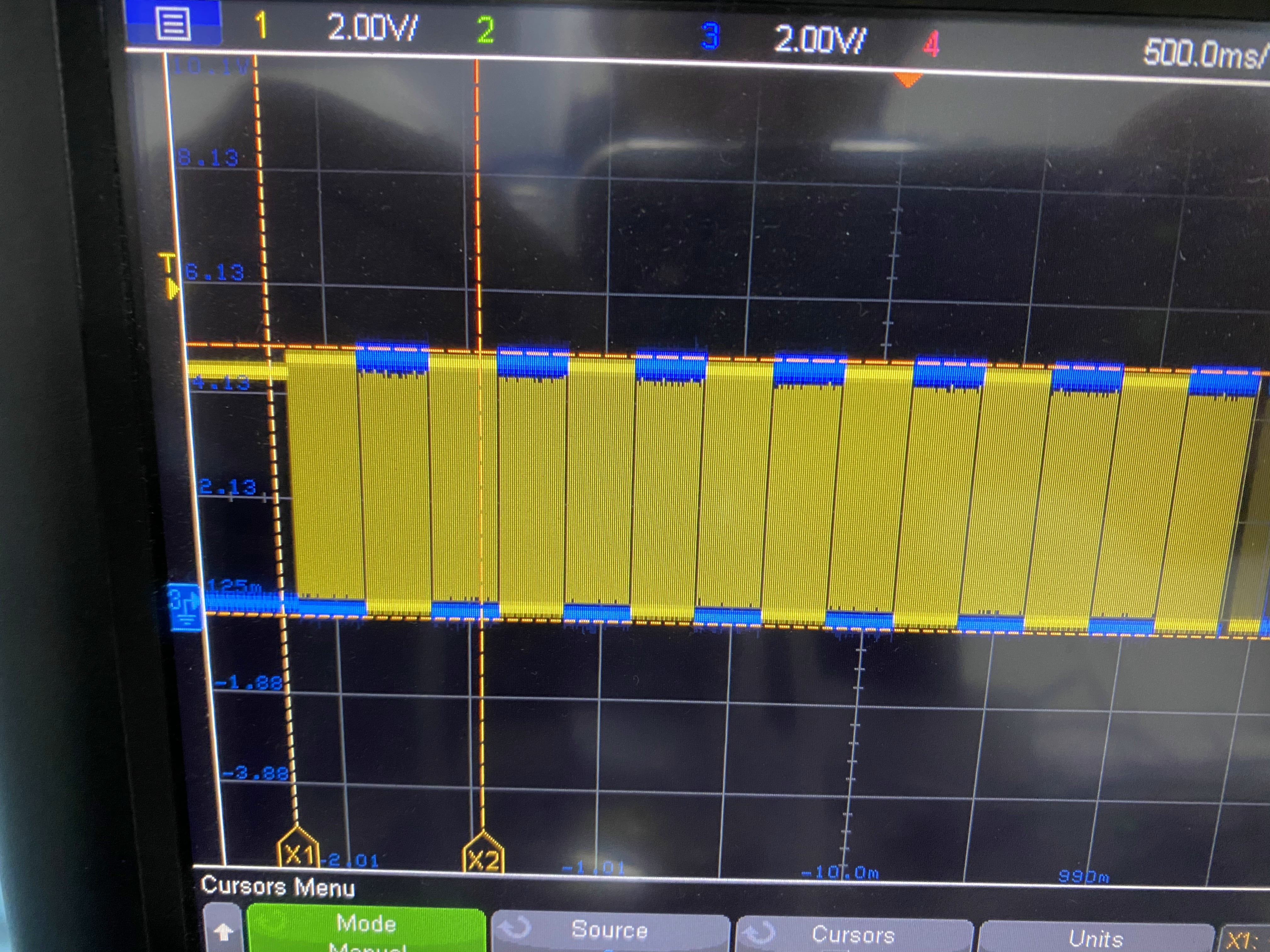
I have replaced OCR4A with 3907 (2Hz) and TCNT4 with 61630 and it works perfectly. The square wave of 2Hz generated is initially LOW.
I have now another issue. I am using the following code to generate a 27kHz--> STEP Pin and 2 Hz --> DIR Pin of a stepper motor:
const byte PULSES = 5;  // Timer 3 "A" output: OC3A --> 27 kHz
const byte DIR = 6;  // Timer 4 "A" output: OC4A --> 2 Hz
boolean a=false;
boolean b=false;
boolean c=false;

void setup() {
  pinMode (PULSES, OUTPUT);
  pinMode (DIR, OUTPUT);
  Serial.begin(9600);

  //  et up Timer 3
  int myEraserPulses = 7;             // this is 111 in binary and is used as an eraser
  TCCR3B &= ~myEraserPulses;   // this operation (AND plus NOT),  set the three bits in TCCR2B to 0
  TCCR3A = _BV(COM3A0) | _BV(WGM31) | _BV(WGM30); // fast PWM
  TCCR3B = _BV(WGM33) | _BV(WGM32); // 16MHz/8=2MHz
  OCR3A =  36;          // 2MHz/22kHz=90.90 (50% duty--> 45)   11kHz=89;  16kHz=61;  22kHz=44; 27 kHz=36;  32kHz=30; 37kHz=26
  TCNT3 = 0;
  TCCR3B |= _BV(CS31); //start timer

  // set up Timer 4
  int myEraserDir = 7;             // this is 111 in binary and is used as an eraser
  TCCR4B &= ~myEraserDir;   // this operation (AND plus NOT),  set the three bits in TCCR4B to 0
  TCCR4A = _BV(COM4A0) | _BV(WGM41) | _BV(WGM40); // fast PWM
  TCCR4B = _BV(WGM43) | _BV(WGM42); // 16MHz/1024=15625Hz
  OCR4A =  3907 ;          // 15625Hz/1Hz=15625 (50% duty--> 7812.5) 1Hz=7812 ; 1.5Hz=5208 ; 2Hz=3907 ; 3Hz = 2604
  TCNT4 = 61630;
  TCCR4B |= _BV(CS42) | _BV(CS40); //start timer

}  // end of setup

void loop() {
//
if (millis()>4660 && a==false && b==false){
   TCCR3A &= ~(_BV(COM3A0));  // Turn off PWM output
   TCCR4A &= ~(_BV(COM4A0));  // Turn off PWM output
   slowDownSTEPPER();
   a=true;
    }
if (millis()>15555 && b==false){
   TCCR3A &= ~(_BV(COM3A0));  // Turn off PWM output
   TCCR4A &= ~(_BV(COM4A0));  // Turn off Dir output
   b=true;
    }
if (millis()>25445 && c==false){
  STEPPER2Hz27kHz();
  c=true;
}

}
void slowDownSTEPPER() {

  int myEraserDir = 7;             // this is 111 in binary and is used as an eraser
  TCCR4B &= ~myEraserDir;   // this operation (AND plus NOT),  set the three bits in TCCR4B to 0
  TCCR4A = _BV(COM4A0) | _BV(WGM41) | _BV(WGM40); // fast PWM
  TCCR4B = _BV(WGM43) | _BV(WGM42); // 16MHz/1024=15625Hz
  OCR4A =  7810 ;          // 15625Hz/1Hz=15625 (50% duty--> 7812.5) 1Hz=7812 ; 1.5Hz=5208 ; 2Hz=3907 ; 3Hz = 2604
  TCNT4 = 57726;
  TCCR4B |= _BV(CS42) | _BV(CS40); //start timer
  delay(250);
  int myEraserPulses = 7;             // this is 111 in binary and is used as an eraser
  TCCR3B &= ~myEraserPulses;   // this operation (AND plus NOT),  set the three bits in TCCR2B to 0
  TCCR3A = _BV(COM3A0) | _BV(WGM31) | _BV(WGM30); // fast PWM
  TCCR3B = _BV(WGM33) | _BV(WGM32); // 16MHz/8=2MHz
  OCR3A =  210;          // 2MHz/22kHz=90.90 (50% duty--> 45)   11kHz=89;  16kHz=61;  22kHz=44; 27 kHz=36;  32kHz=30; 37kHz=26
  TCNT3 = 0;
  TCCR3B |= _BV(CS31); //start timer

}

void STEPPER2Hz27kHz() {

  int myEraserDir = 7;             // this is 111 in binary and is used as an eraser
  TCCR4B &= ~myEraserDir;   // this operation (AND plus NOT),  set the three bits in TCCR4B to 0
  TCCR4A = _BV(COM4A0) | _BV(WGM41) | _BV(WGM40); // fast PWM
  TCCR4B = _BV(WGM43) | _BV(WGM42); // 16MHz/1024=15625Hz
  TCNT4 = 61630;
  OCR4A =  3907 ;          // 15625Hz/1Hz=15625 (50% duty--> 7812.5) 1Hz=7812 ; 1.5Hz=5208 ; 2Hz=3907 ; 3Hz = 2604
  TCCR4B |= _BV(CS42) | _BV(CS40); //start timer

  int myEraserPulses = 7;             // this is 111 in binary and is used as an eraser
  TCCR3B &= ~myEraserPulses;   // this operation (AND plus NOT),  set the three bits in TCCR2B to 0
  TCCR3A = _BV(COM3A0) | _BV(WGM31) | _BV(WGM30); // fast PWM
  TCCR3B = _BV(WGM33) | _BV(WGM32); // 16MHz/8=2MHz
  OCR3A =  36;          // 2MHz/22kHz=90.90 (50% duty--> 45)   11kHz=89;  16kHz=61;  22kHz=44; 27 kHz=36;  32kHz=30; 37kHz=26
  TCNT3 = 0;
  TCCR3B |= _BV(CS31); //start timer

}
After generating 27kHz-2Hz in the void setup, I want to slow down the motor after more or less 5 seconds. Then my goal is to stop the motor and restarting it after 15 seconds with the initial 27kHz-2Hz.
I am successfully performing the initial start and the slowing down but not the restart. Indeed when the motor restarts (even if the code to generate the 27kHz-2Hz restart is equal to the initial start), the 2 signals I got in output on STEP and DIR pins are different. The 2Hz is initially HIGH for 750 ms, whereas with the initial start is LOW for 250 ms.
I need the signal to be initially LOW as it is during the initial start.
I suspect this happens because I stop the motor while is running and TCNTx has some value saved inside while in the beginning it starts from the default value.