I have not purchased the Arduino MEGA 2560 R3 yet.. just looking online at the specs..
and noticed in the pin mapping page for the 2560 Arduino MEGA:
..there are 18 PWM-pins:
0,1,2,3,4,5,6,7,8,9,10,11,12,16,17,51,52,53
but the overview page it says: "of which 14 can be used as PWM outputs"
below on the spec page it says:
"Digital I/O Pins - 54 (of which 15 provide PWM output)"
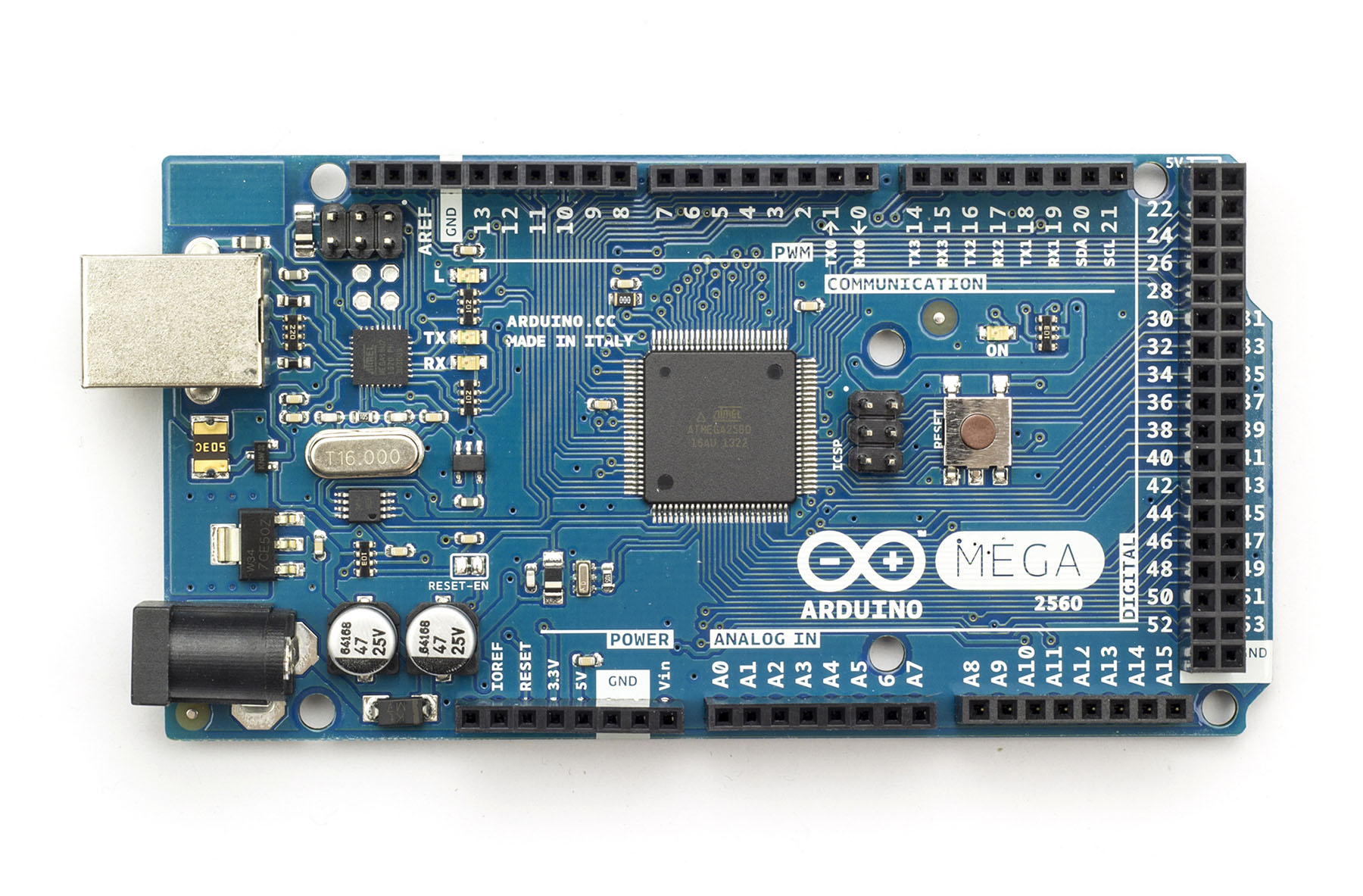
now which are the 14 or 15 you can actually use? --because in the photo image you see 12 digital pins that are at the top row, which is indicated as "PWM" :
also curious if you could change via code some of the other digital inputs to PWM or write a program routine that makes a "normal" digital output a PWM output -- possible?
if it is how would the code look like?