Arduino Mega Resets Randomly During Operation

I am having issues while running my program. My Arduino Mega 2560 resets randomly. At times, it will reset in the setup portion of the code, at other times it will reset during the loop function. It happens randomly, not at consistent parts of my code. Also, it seems as though if I power down the device and leave it off for a week or so, the issue happens more frequently than if it has been running for a few minutes/hours.

The machine I am working on has 8 12v solenoids controlled in pairs with 4 mechanical relays. There are also 3 12v lights on a light stack controlled individually by the same type of relays. Each of the 7 relays are powered from an external power supply (5v 60a + 12v 30a) with their signal and ground going to the Arduino. There are also 4 servo motors which are again powered directly from that same 5v power supply with their common ground and signal going to the Arduino. Additionally, there are 2 inductive sensors implemented in the same way being powered separately from the Arduino. I am no expert at any of this by any means but I have spent quite a bit of time trying to figure this issue out on my own before posting about it here and have learned some things along the way to help improve my code and setup. I will paste my code below and answer any follow up questions necessary. Could someone please help me figure out what might be causing this random reset? Is it my code? Is there something I can do with my Arduino to prevent this?

#include <Servo.h>

Servo left;
Servo right;
Servo shoot;
Servo chop;

int RetractRLY = 3; //Relay3
int PushRLY = 4; //Relay4
int LiftRLY = 5; //Relay1
int DropRLY = 6; //Relay2

int REDRLY = 8;
int YLWRLY = 9;
int GRNRLY = 10;
int pauseButn = 11;
int startButn = 12;

int PushInitPosSens = 55; // PushInitPosSens
int MidPosSens = 56;//Sens3

int ServoPower = 60;

bool ServoPowerOn = 0;


void setup() {
  shoot.attach(54);
  chop.attach(57);
  right.attach(58);
  left.attach(59);


  int StuckTime;
  bool PusherINITpos = digitalRead(PushInitPosSens);
  Serial.begin(115200);

  pinMode(LiftRLY, OUTPUT);
  pinMode(DropRLY, OUTPUT);
  pinMode(RetractRLY, OUTPUT);
  pinMode(PushRLY, OUTPUT);
  pinMode(PushInitPosSens, INPUT_PULLUP);
  pinMode(ServoPower, OUTPUT);
  pinMode(MidPosSens, INPUT_PULLUP);
  pinMode(REDRLY, OUTPUT);
  pinMode(YLWRLY, OUTPUT);
  pinMode(GRNRLY, OUTPUT);
  pinMode(pauseButn, INPUT_PULLUP);
  pinMode(startButn, INPUT_PULLUP);


  chop.write(57);
  Wait(150);
  shoot.write(120);
  Wait(150);
  Grab();
  Wait(150);
  digitalWrite(ServoPower, HIGH);
  Wait(150);
  Lift();
  Wait(150);
  UNGrab();
  Wait(200);

  while (PusherINITpos == 1) {
    digitalWrite(RetractRLY, HIGH);
    PusherINITpos = digitalRead(PushInitPosSens);
    StuckTime = millis();
    if (StuckTime > 6000) {
      goto MoveOn;
    }
  }

MoveOn:
  digitalWrite(RetractRLY, LOW);
  Push1();
  Wait(300);
  Push2();
  Wait(300);
  MidPos();
  Wait(300);

}

void loop() {
  bool StartState = digitalRead(startButn);
  bool StopState = digitalRead(pauseButn);
  unsigned long startTime;
  unsigned long endTime;
  float DeltaTime;
  float CycleTime;

  while (StartState == 1) {
    startTime = millis();
    //Serial.println(startTime);
    GREEN();
    StartPos();
    Wait(100);
    Chop();
    Wait(400);
    Push1();
    Wait(100);
    MidPos();
    Wait(150);
    Grab();
    Wait(300);
    Drop();
    Wait(200);
    SHOOT();
    Wait(250);
    Lift();
    Wait(75);
    UNGrab();
    Wait(150);
    Push2();
    Wait(100);
    endTime = millis();
    //Serial.println(endTime);
    DeltaTime = (endTime - startTime);
    //Serial.println(DeltaTime);
    CycleTime = DeltaTime / 1000;
    Serial.print("Cycle time: ");
    Serial.print(CycleTime);
    Serial.print(" Sec");
    Serial.println("");

    StopState = digitalRead(pauseButn);
    if (StopState == 1) {
      StartState = 0;
      MidPos();
      LightsOut();
    }
    else {
      StartState = 1;
    }

  }


}

void Drop() {
  (digitalWrite(DropRLY, HIGH));
  Wait(400);
  (digitalWrite(DropRLY, LOW));
  Wait(150);

}

void Push2() {

  digitalWrite(RetractRLY, LOW);
  digitalWrite(PushRLY, HIGH);
  Wait(1000);
  digitalWrite(PushRLY, LOW);
  Wait(30);


}

void Push1() {
  bool PusherMIDpos = digitalRead(MidPosSens);

  while (PusherMIDpos == 1) {
    digitalWrite(PushRLY, HIGH);
    PusherMIDpos = digitalRead(MidPosSens);
  }
  digitalWrite(PushRLY, LOW);

}

void Chop() {
  chop.write(57);
  Wait(50);
  chop.write(130);
  Wait(700);
  chop.write(57);

}

void Grab() {
  const int leftgrab = 110.5;//amount of grab for left finger
  const int rightgrab = 69;//amount of grab for right finger
  left.write(leftgrab);
  Wait(150);
  right.write(rightgrab);
}

void UNGrab() {
  left.write(130);
  right.write(50);
}

void Lift() {
  digitalWrite(LiftRLY, HIGH);
  Wait(500);
  digitalWrite(LiftRLY, LOW);
}

void YELLOW() {
  digitalWrite(REDRLY, LOW);
  digitalWrite(YLWRLY, HIGH);
  digitalWrite(GRNRLY, LOW);
}


void RED() {
  digitalWrite(REDRLY, HIGH);
  digitalWrite(YLWRLY, LOW);
  digitalWrite(GRNRLY, LOW);
}


void GREEN() {
  digitalWrite(REDRLY, LOW);
  digitalWrite(YLWRLY, LOW);
  digitalWrite(GRNRLY, HIGH);
}

void LightsOut() {
  digitalWrite(REDRLY, LOW);
  digitalWrite(YLWRLY, LOW);
  digitalWrite(GRNRLY, LOW);
}

void SHOOT() {
  shoot.write(91);
  Wait(300);
  shoot.write(120);
}

void MidPos() {
  bool PusherINITpos = digitalRead(PushInitPosSens);

  while (PusherINITpos == 1) {
    digitalWrite(RetractRLY, HIGH);
    PusherINITpos = digitalRead(PushInitPosSens);
  }
  digitalWrite(RetractRLY, LOW);

}


void StartPos() {
  digitalWrite(RetractRLY, HIGH);
  Lift();
  Wait(100);
  digitalWrite(RetractRLY, LOW);


}

void Wait(int duration)
{
  unsigned long CurrentTime;
  unsigned long PastTime;


  CurrentTime = millis();
  PastTime = millis();


  while (CurrentTime - PastTime <= duration) {
    CurrentTime = millis();
    //Serial.println(CurrentTime);
  }
  PastTime = CurrentTime;
}

Random resetting of a processor is caused through EMI (electro magnetic interference).
This happens when motors, solenoids and other inductive components turn off. It is not normally connected to the code.

There are ways to suppress this interference, what measures have you taken to prevent EMI?

It is best if you show a schematic of your circuit, hand drawn is fine Fritzing is not.

Hi, @askchemicals
Welcome to the forum.

Can you please post a schematic of your project, including power supplies?
Can you please post some images of your project so we can see your component layout?

With your gnd connection from the power supply to the Mega, is it a direct connection and not via gnds from the hardware that you are using?
What I'm trying to say, is there a part of your wiring when the gnd current from the hardware and gnd current from the Mega share the same wire, rather than a "star" type connection at the power supply, which is preferred.

Tom.. :smiley: :+1: :coffee: :australia:
PS. I'm off to bed, G'dnight... :smiley: :sleeping: :sleeping: :sleeping: :sleeping: :sleeping:

Thank you for your quick response!

I apologize, it keeps telling me that new users are not allowed to upload documents. I will keep trying because I understand that it is necessary.

I am not sure if I can explain it in words but I will try. These are the relays I am using currently:

They all share a power bus for their 5v power coming directly from my 5v power supply. The signal wires go to their respective pins on the Arduino. The lights and solenoids are all wired to the relays on their separate 12v circuit with the common and NO ports on the relay. The servo motors and inductive sensors also share that same 5v bus with their signals going to their respective pins on the Arduino. The Arduino is powered from the same 5v supply but off of two different terminals and it shares the gnd with that 5v bus.

EMI is an interesting thing to bring up, I had not considered it. All I have done so far is add a capacitor to the power for the Arduino thinking it might be dipping in power and add a pullup resistor to the reset circuit thinking it could also be dipping in power. My thoughts were that because these relays use a signal wire to trigger them, EMI should not be in effect but I could certainly be wrong. I have not done anything with the servo motors. What would you suggest?

(Again, I will continue to try to upload my schematic)

Thank you as well for your quick response. I was just writing to Grumpy_Mike about how new users are not allowed to post documents for some reason. I will continue to try to get documents uploaded but in the meantime, I have the Arduino powered with 5v + and - from the power supply. The one I am using has multiple terminals so I know it is a good connection with a ferrule connector on it. I do also have a shared wire from the components gnd to the Arduino gnd for giggles after wondering if it was a problem with that.

Relays and solenoids need antikickback diodes across the coils. Most "Arduino compatible" blue cube relays have them built in, most solenoids do not. Your power supply needs to be solid and have plenty of headroom. most usb power supplies are "soft" and may sag enough during a solenoid kick to reset the cpu.
Your power source sounds like a PC power supply. 5V @ 60A needs at least 5% load to stay in regulation. 5% of 60A is 3A, I'll bet your 5V draw is a fraction of that.

@askchemicals
You're at Trust Level 0. Please visit this page:
New User Limits
As explained there, you need to do something to achieve Trust Level 1, namely

Trust Level 1 -- Basic

At Discourse, we believe reading is the most fundamental and healthy action in any community. If a new user is willing to spend a little time reading, they will quickly be promoted to the first trust level.

Get to trust level 1 by…

  • Entering at least 5 topics
  • Reading at least 30 posts
  • Spend a total of 10 minutes reading posts

Users at trust level 1 can…

  • Use all core Discourse functions; all new user restrictions are removed
  • Send PMs
  • Upload images and attachments if enabled
  • Edit wiki posts
  • Flag posts
  • Mute other users
    Admins can change these thresholds by searching for tl1 in site settings.

It's not that hard to do, and you might just learn something along the way about how this forum functions! See you soon!

This is my 5v power supply:

I would certainly say I have headroom here. My purpose for going this big was to ensure that not enough power was not going to be an issue as well as to leave enough room for expansion in the future. I did however only upgrade to something this big because a smaller power supply was doing the same thing. I would agree my draw is a very small amount on startup but when I have everything switching on and off and 4 20kg servo motors moving I think meeting 3A should not be too difficult. That being said, you say the power supply is out of regulation, I measure a consistent voltage while it is off and while it is running, what do you think this is doing regarding the resetting issue? The capacitor I have on there with the on-board voltage regulator isn't cleaning that up enough to work properly?

(Edit) The power supply manufacturer states that it has a synchronous rectifier smart chip and EMI filter which are meant to regulate the 5v at any draw

Your devices are all 12V loads. only the LOGIC is using the +5. put an ammeter on it and find out.


Don't guess, measure!

Much conjecture could be resolved with a schematic. You know how to get to the point where you can post one.
Good luck with your project!

It is a regulating power supply. The current draw does not matter unless it is above 300 Watts which it is not. Also, are you measuring current in parallel lol?!? You measure current in series with the rest of your power drawing components.

Here is a copy of my schematic
Schematic.pdf (138.4 KB)

Switched power supplies need a minimum load for regulation. Its the 5v @ 60a that may be too lightly loaded. measure the 5v draw and SEE.

1 Like

@madmark2150 is absolutely correct, by the way. You can under-load a switcher, it depends upon the particular design.
Second point - for those using Arduino Mega, is it viable to supply Vin with +5, or will that result in the Mega running at 4.x, resulting in noise susceptibility at the best, failure at worst? I don't use my Mega. With my Nano units, that's expressly a no-no, the Nano will work sporadically at best; if you have 5V available, it's best to directly feed the 5V pin.

By the way, thanks for the schematic, it is very illuminating!

Third point - do those solenoid valves have diodes across their solenoids? If not, best to add them, because when they shut off, they WILL emit a significant transient.

I use meanwell 5V / 3A power supplies to feed a Power Distribution Board that piggie backs to the Mega.


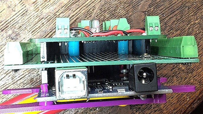
It has screw terminals and bypass caps.
https://create.arduino.cc/projecthub/madmark2150/perf-panel-paired-power-plug-piggyback-for-mega-2560-uno-67d604

I repeat the question:

Does the Mega design differ from the Nano? Can you feed Vin (a specific pin) with 5V reliably? Or should you feed 5V directly, bypassing the regulator? because the OP's drawing specifically shows 5V to Vin, and his complaint is noise, resets, etc. which I would absolutely expect if I powered my Nano that way.

Hi, @askchemicals
Thanks for the schematic.

Thanks.. Tom... :smiley: :+1: :coffee: :australia:

A little bit.
No.
Yes.

Then, until the OP fixes that, all other theories are wasted breath. Unless he mislabelled his schematic, he's feeding the Arduino 5V via Vin.
Case suspended, for now.

1 Like