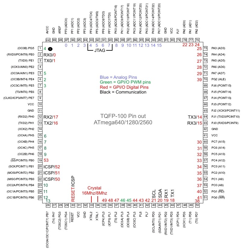
I am working on a Arduino Mega Variant and I did a pin map for the TQFP Pinout.
First I would like a second set of eyes and please let me know If I am missing anything or if there is something incorrect.
Second, I would like to know why only 70 GPI/Os are used and not all 86?
As you can see, Other than the obvious GND or VCC there are 16 pins not connected to anything and if you add up the GPI/Os used, 54 Digital + 16 Analog = 70. The Datasheet states there are 86 GPI/Os, 86 - 70 = 16 pins not used.
Are these pins available in the software, but just didn't fit the design on the Arduino MEGA baord?
Third, I think the RX0/0 and TX0/1 is incorrect. The data sheet does not state that Pins 2 and 3 are pwm pin outs and all other pwms are listed as a clock, i.e OC1A or OC2A. so which pins are actually pwm 0 and 1? NOTE: this has been correct, see post below. Image also is corrected.
Also, Pins 38, 39, 40 should be PWM 16 bit pins, but they are not shown as such. instead the mega uses 3 of the 8 bit PWMs, pins 1, 18, and 23. The 16 bit PWMs have 3 channels (i.e. OC1A, OC1B, OC1C) and the 8 bits only have 2 channels.
Third, I think the RX0/0 and TX0/1 is incorrect. The data sheet does not state that Pins 2 and 3 are pwm pin outs and all other pwms are listed as a clock, i.e OC1A or OC2A. so which pins are actually pwm 0 and 1?
UPDATE: after doing some testing, pins 2 and 3 (RX0 and TX0) are NOT PWM pins, but act as Digital I/Os.
The other 2 PWMs are pins 38 and 39, or Digipin 46 and 45. Why who ever did it this way I don't know, and why the 3rd PWM, pin 40 was not included??, or perhaps the schematic is simply worng. Arduino MEGA
EDIT
That gives us 14 PWM pin outs, 2 short of the 16 total available (actually 15, as pin 26 is shared with OC0A and OC1C).
You could get all of them working through direct port manipulation or code in to make them work with digitalWrite.
I presume it is similar to the duemilanove where two of the possible analog pins have been missed off so that it looks nice and fits the format of the board. The seeduino 328 board has the extra analog pins...
The Datasheet states there are 86 GPI/Os, 86 - 70 = 16 pins not used.
Are these pins available in the software, but just didn't fit the design on the Arduino MEGA baord?
The Arduino Mega doesn't support those 16 extra I/O pins, not in the hardware nor in the core library software pin definitions. The Seeeduino Mega board does run those extra pins to additional connectors, but because the Arduino IDE does not support those pins, you can only access them using direct port access commands.
I presume it is similar to the duemilanove where two of the possible analog pins have been missed off so that it looks nice and fits the format of the board. The seeduino 328 board has the extra analog pins...
Isn't it only the SMD chips that have the two extra pins? Pretty sure all of the pins of the DIP '328 have been brought out.
And another question,
Why waste a pin with an on board LED on pin #13? I assume this is simply for Tutorial/training purposes and there is no real need for the LED on pin 13. Although I can see how it could be used for Visual indication that the code is running properly.
My variant is going to be as small as posible, so it may go if I need the room.
Pin 13 is not really wasted in the standard Arduino board design because of using a on-board resistor/LED wired to pin 13. The digital I/O pin from the AVR chip is also wired straight to the standard pin 13 at the connector.
One could, in their sketch, make the mode of the pin an input pin, however the external signal wired to the pin 13 would have to have enough current drive to drive the resistor/led at the same time as the input pin reads the signal. The resistor/LED combination is in effect acting as a pull-down load for external high signals.
If one, in their sketch, makes the mode of the pin 13 an output pin then the signal would still be sent to the pin13 connector and would also turn on or off the on-board led at the same time.
So except for the current drive requirment to utilize pin 13 as an input for external signals, there is no 'waste' of pin 13.
I can't get that to compile, I get the following compile error:
from C:\Documents and Settings\Primary Windows User\My Documents\My Program Files\Arduino\arduino-0018\hardware\arduino\cores\arduino\pins_arduino.c:29:
c:/documents and settings/primary windows user/my documents/my program files/arduino/arduino-0018/hardware/tools/avr/lib/gcc/../../avr/include/avr/pgmspace.h:215: error: expected '=', ',', ';', 'asm' or 'attribute' before 'prog_int8_t'
Unless the Arduino team was to make the 16 pin additions 'official' I'm not too interested in modifying just my IDE, too much loss of portability in my opinion. I'm satisfied with using direct port access commands to access the additional 16 pins that the Seeeduino provides.