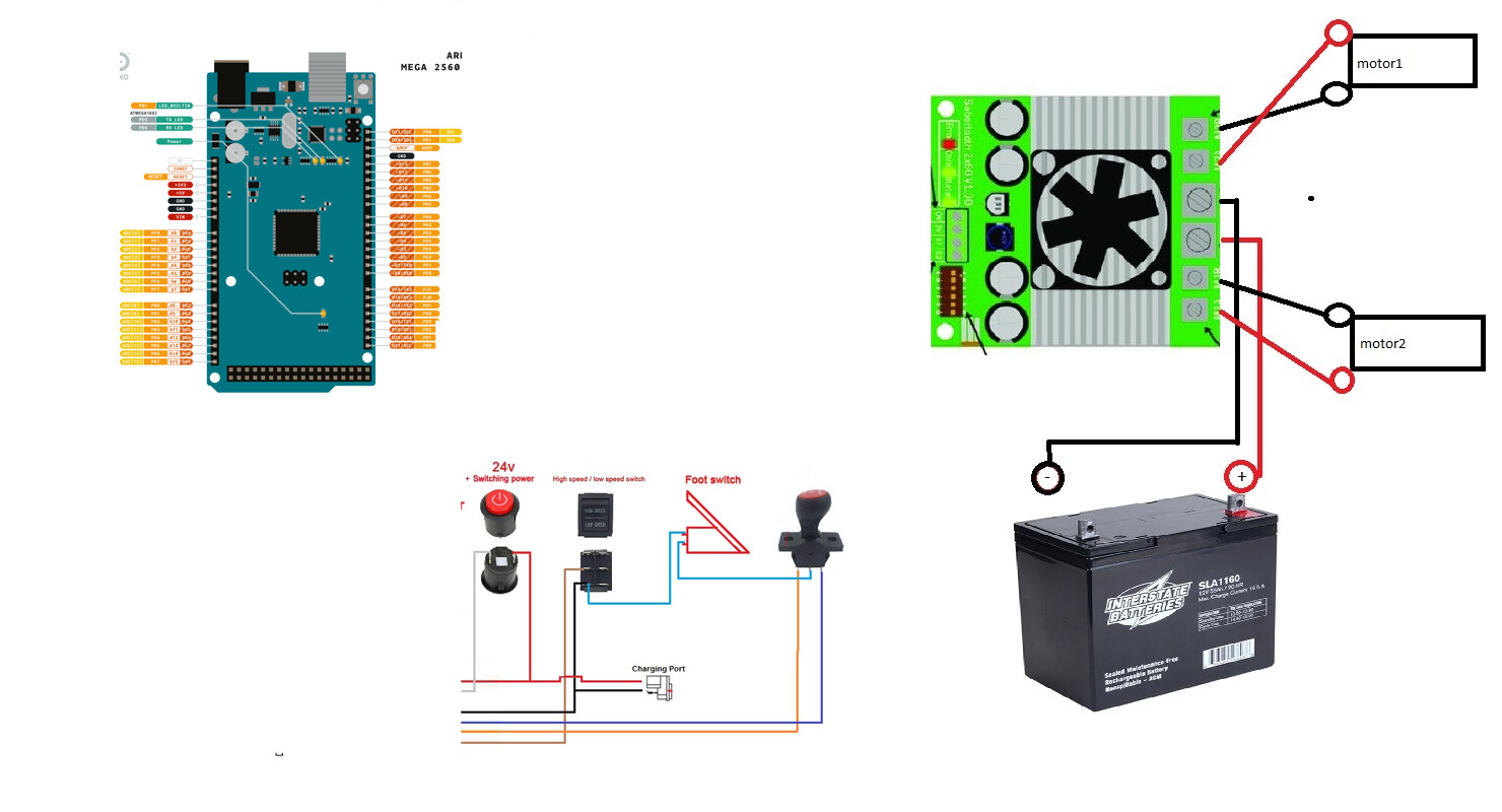
Let me try and get myself caught up, I am starting to get lost. But currently i am not getting feedback at all from the pedal (which is because of the wiring). I wired the battery and motors to the sabertooth exactly as they are on the diagram, I used the 5v and gnd on the sabertooth to power the arduino. From the 7 pin connector I cut and landed R to D2 and F to D3 on arduino, GND to arduino GND. Now the remaining 7 pin wires - battery positive, power output, and high/low switch are not landed at all.
No it does not. I misread a series current limiting resistor's roll in the circuit, it's for the heart beat and the wiring of the speed pot will recur un as much range as it can, which mayn't be 0 to 1023 for mechanical reasons.
a7
Sealed lead acid type? If so, I misunderstood yesterday and DIP switch 3 should be in the UP position (down is only for lithium polymer type)
Let me add to that. Here's a reworked code based off Dimension Engineering's Sabertooth example code for Simplified Serial. Honestly, there's no reason to use software serial that I'm aware of. Be sure to read the code through before using.
/*********** Powerwheels Sabertooth *********************

    !!!!!!!!!!!!!!!  IMPORTANT  !!!!!!!!!!!!!!!
    !!!!!!!!!!!!!!!  IMPORTANT  !!!!!!!!!!!!!!!
    !!!!!!!!!!!!!!!  IMPORTANT  !!!!!!!!!!!!!!!

  THIS CODE WILL ALLOW OVERRIDING OF KID'S RIDE ON TOYS
  SUCH AS THOSE MADE BY POWERWHEELS AND PEG PEREGO

  IT IS UNTESTED CODE IN ACTUAL RIDE ON WITH RIDER.
      USE AT YOUR OWN RISK!
  DO NOT, I MEAN DO NOT USE ON RIDE ON TOY WITH ANY
  RIDER UNTIL IT HAS BEEN CALIBRATED AND THOROUGHLY
  TESTED TO THE SATISFACTION OF A COMPETENT ADULT
  CARE PROVIDER FOR THE RIDER IF THE RIDER IS NOT AN
  ADULT.

  THIS CODE CONTAINS NO EMERGENCY OVERRIDE AND THE TOY
  SHOULD ONLY BE OPERATED WITHIN THE REACH OF A
  COMPETENT ADULT CARE PROVIDER WHERE A MECHANICALLY
  OPERATED EMERGENCY STOP OVERRIDE DEVICE HAS BEEN INSTALLED,
  EFFECTIVELY REMOVING ALL BATTERY POWER TO THE MOTORS.

  END OF IMPORTANT NOTE

   ---------  INSTRUCTIONS TO BUILDER  ------------
        Requires changes to code depending on your hardware
        if using two position button type pedal, activate
        the line
        pinMode(sensorPin, INPUT_PULLUP);
        by uncommenting it.
        if using typical potentiometer, leave that line
        commented out.

        Also, in function void checkSpeedPot(){}
        have a read through and there's some stuff to set there
        Defaults to testing (printing data to PC over Serial)
        and assumes pushbutton type "all-or-nothing"
        throttle input. These can be adjusted according to
        the notes above and the comments found throughout
        this sketch.

  The circuit:
  - potentiomenter to analog input 0
  OR if you use a switch type pedal
  - switch pin A0 to GND
  - forward switch to D3
  - reverse switch to D4
  - LED on digital pin 13 to ground
  - view values in Serial monitor, 9600 baud
  - Arduino TX to Sabertooth S1
  - Arduino RX to Sabertooth S2

  Tested with 2 x Razor scooter brushed motors and seems
  to be working as expected.

  Sabertooth DIP switch settings for this Packetized Serial Mode:
   - 1: D for Packetized Serial address 128
   - 2: D
   - 3: D for LiPo, U for all other chemistries (battery cutoff switch)
   - 4: U for 9600 baud, reverse this for 19200 baud: baud select pin 1 U for autobaud
   - 5: U for 9600 baud, reverse this for 19200 baud: baud select pin 2
   - 6: U for Standard Simplified Serial

  by Hallowed31
  2024-07-27

  Library copyright Dimension Engineering, 2012
    "Copyright (c) 2012 Dimension Engineering LLC
    See license.txt for license details."
*/


#include <Sabertooth.h>
Sabertooth ST = Sabertooth(128); // address 128

#define PUSHED LOW
#define RELEASED HIGH

const int maximum = 1017;
const int minimum = 13;
const byte speedPot = A0;
const byte heartbeatLED = 13;
//Hardware Serial connected to 1;
const byte backwardSwitch = 3;
const byte forwardSwitch = 4;

//10 * 50ms = 500ms (1/2 second) before a change is validated
const byte debounceAmount = 10;

//when counters reach 10 (i.e. 10 read cycles) we assumed a valid switch change
byte forwardCounter = 0;
byte backwardCounter = 0;

byte lastForwardSwitch = RELEASED;
byte lastBackwardSwitch = RELEASED;

enum { REVERSE = -1,
       NEUTRAL = 0,
       FORWARD = 1
     };

int directionFlag = NEUTRAL;
int speed = 0;
int m1 = 0; // signal to motor 1
int m2 = 0; // signal to motor 2

unsigned long heartbeatTime;
unsigned long checkSwitchesTime;
unsigned long checkSSpeedPotTime;

void setup() {
  Serial.begin(9600);
  SabertoothTXPinSerial.begin(9600);
  Sabertooth::autobaud(SabertoothTXPinSerial);
  // the line below is for a button type pedal
  // comment this out if using potentiometer
  pinMode(speedPot, INPUT_PULLUP);
  pinMode(forwardSwitch, INPUT_PULLUP);
  pinMode(backwardSwitch, INPUT_PULLUP);
  pinMode(heartbeatLED, OUTPUT);
}

void loop() {
  if (millis() - heartbeatTime >= 500ul) { //500ms
    heartbeatTime = millis();
    digitalWrite(heartbeatLED, !digitalRead(heartbeatLED));
  }

  if (millis() - checkSwitchesTime >= 50ul) { //50ms
    checkSwitchesTime = millis();
    checkSwitches();
  }

  if (millis() - checkSSpeedPotTime >= 100ul) { //100ms
    checkSSpeedPotTime = millis();
    checkSpeedPot();
  }

  /************************************************
    Other non blocking code goes here.
    That means no while(), no delay();
  *************************************************/

}

void checkSwitches() {
  // forward switch
  byte state;
  state = digitalRead(forwardSwitch);
  if (lastForwardSwitch != state) {
    forwardCounter++;
    if (forwardCounter >= debounceAmount) {
      //get ready for the next cycle
      forwardCounter = 0;
      lastForwardSwitch = state;
      if (state == PUSHED) {
        directionFlag = FORWARD;
      }
      else {
        directionFlag = NEUTRAL;
        // ST.drive(0);
      }
    }
  }
  else {
    forwardCounter = 0;
  }

  // backward switch
  state = digitalRead(backwardSwitch);
  if (lastBackwardSwitch != state) {
    backwardCounter++;
    if (backwardCounter >= debounceAmount) {
      backwardCounter = 0;
      lastBackwardSwitch = state;
      if (state == PUSHED) {
        directionFlag = REVERSE;
      }
      else {
        directionFlag = NEUTRAL;
        //ST.drive(0);
      }
    }
  }
  else {
    backwardCounter = 0;
  }
}

void checkSpeedPot() {
  speed = analogRead(speedPot);

  // uncomment for testing, comment out for final install
  // printRawData();

  /* IMPORTANT - use only ONE of these speed = map(etc) functions at at time */
  // for potentiometer type throttle
  // speed = (map(speed, minimum, maximum, 0, 1023)) / 8;  //for speed 0 to ±127

  // for pushbutton type throttle, map is reversed because INPUT_PULLUP
  speed = (map(speed, minimum, maximum, 1023, 0)) / 8;  //for speed 0 to ±127

  // uncomment for testing, comment out for final install
  //  printMappedData();
  speed = constrain(speed, 0, 127);  //for speed 0 to ±127
  speed = directionFlag * speed;
  m1 = speed;
  m2 = speed;
  // uncomment for testing, comment out for final install
  //  printFinalDriveSignal();

  ST.motor(1, m1); // motor 1, speed cast to m1
  ST.motor(2, m2); // notor 2, speed cast to m2
}

void printRawData() {
  Serial.print("Throttle Input: ");
  Serial.print(speed);
  Serial.print(" ");
}
void printMappedData() {
  Serial.print("Throttle Mapped To: ");
  Serial.print(speed);
  Serial.print(" ");
}
void printFinalDriveSignal() {
  Serial.print("  Final Drive Signal M1: ");
  Serial.print(m1);
  Serial.print("  Final Drive Signal M2: ");
  Serial.println(m2);
  Serial.println();
}
EDIT code is not what i posted a few hours ago. This version seems to be working as expected, tested with 2x25 Sabertooth on 2 Razor scooter motors.
Note the DIP switch changes and wiring; it is different from before.
I don’t think I have the wire ran for the heartbeat
Yes for now, at some point I’d like to switch to milwaukees
I don't love that. A buck converter set to +7V between the battery and the Arduino, to power the Arduino itself, would be preferable.
Ok, so I think there's some confusion though on my end. You are NOT using a Sabertooth 2x60 as a motor driver or you are? What is a WEELYE? Is that you motor driver? The picture says "receiver" which - what the what?
If the WEELYE is the stock motor driver for the Power Wheels (I don't know, I only ever worked on Peg Peregos), then you don't need it at all.
Pedal (switch) to A0 Arduino. It won't connect to the motor driver at all. You're trying to send Serial, not analog signals to the motor driver, right?
All switches go to the Arduino and are read there. All the Arduino is connected to is the Sabertooth (assuming that's what you're using). Two wires (three if you insist on using the ST +5V): (maybe) +5V, GND, TX (D1 or 11 depending on hardware or software serial - the code I supplied uses hardware, ie pin D1 Arduino to S1 Sabertooth)
I don't know what "landed" means. Do I sound like an AI? You never can tell these days...
It's just the LED on pin 13. Don't actually need it, it's just a visual indication which you'll either route to the dashboard or if you don't, probably won't see anyway. Certainly the rider should probably have their eyes on the road anyway...but it's your call.
I am replacing the weelye (factory board) with the sabertooth. But I was trying to utilize as much of the wiring as I could.
Which wire would be the pedal switch to A0?
Hooked up. Here I am trying to sound smart ![]()
Just caught this, too. Definitely do not use software serial. Use the second hardware serial port on the Mega. I'll revise the code to reflect that
Only 2 wires coming off pedal. One goes to GND on high/low switch. Other goes to middle/park position on the fwd/rev selector
Are you using an Arduino Mega and Dimension Engineering Sabertooth 2x60 or not?
A button (which that pedal is) is a button. If you want a variable speed pedal, you have to make one.
EDIT: sorry very sleepy today. Yes, that switch arrangement works but you want to pick each line off to a different Arduino pin IN, define states for each button read. At least that's how I'd do it. then the sketch I already supplied, just make the one switch state always NEUTRAL, the other FORWARD and the last REVERSE.
Maybe it's a thing. Hey man, I'm an amateur Dad-Builder-hobbyist myself and I was once where you are in terms of coding Arduino. In terms of electrical circuits, I'm still pretty beginner there; I rely a lot on ready-built modules since I get little joy out of making my own circuit boards.
Some of the helpers here are heavier on the electronic circuits, some on the Arduino/C/C++ coding, and some are real gurus who excel at both.
I don't have all your same parts in front of me to tinker around with, a lot of what I'm advising is going on in my head and based on similar projects I did for my kids, but a lot of that ready expertise has been lost to the time on my old memory

Ok ok, glad to clear that up. Don't use the WEELYE board at all. There's 64% of your confusion there (exactly 64% btw, don't question this number ![]() ) .
) .
So your car has power assist steering? That's a bit of a gremlin for me since I've only seen PW toys with mechanical steering and two drive motors.
All switch wires on the Arduino go one side to whatever pin you have in the code and the other to ground. Then in void setup() we do
pinMode(whateverSwitch, INPUT_PULLUP);
and the 10k pullup resistors built into the AVR Arduino boards get used, saving adding pullup or pulldown resistors yourself. You just have to keep in mind that doing this means that pressing a typical pushbutton becomes close to 0V, logical LOW and releasing is close to VCC, logical HIGH. So reverse the standard button logic in the code to account for this physical, electrical change.
What reason do you have for keeping the original controller board? The Arduino and Sabertooth can do everything it did (except maybe that steering motor, but you could always get some terminal strip at the hardware store, make a 24V line, a fused (yes do this) master power rocker switch after the battery positive to the terminal strip, then in parallel wire 24V to the Sabertooth and the Weelye, using the Weelye for nothing at all except that steering motor.
Oh, note that if you're using 2x12V batteries in series, you wire that as a split load but keep the fuse and charging port on the 24V side, the port before the master switch. Then just turn the thing off to charge.
At your local electrical supply house, buy a ground lug and return all grounds, including the battery ground to it.
So you'll have a 2x12V in series rail, and a 1x12V (pick one of the batteries) rail if you go like this. Then use a buck converter to dial down that 12V to 7 or 9V, use that to power the Arduino.
You could even use the 12V rail to add 12V auto accessories like an LED light bar or clown horn or something.
That code I posted assumes one switch. Just use the calibrate one and try each switch individually to get your min max values, then hard code their individual purpose into the driver code I supplied.
I wrote a code similar using RC signals for another fellow here a couple days ago, using it and the version of ST I posted here, shouldn't be too arduous to knock together.
You also could replace that pedal altogether with something like this
and as long as it's 0-5V, you just have one position on the shifter and variable, proper speed control.
You don't even need to do that. With your existing pedal, the Sabertooth does that for you if you set the DIP switch for exponential response.
I can say that my 2x60 controller is going on 10 years old, served me FLAWLESSLY in even my 250-ish pound, electric wheelchair based robot.
weelye is gone
Yes it does, but honestly I am not even worried about that right now.
My idea was to cut out the weelye board and keep all the existing wiring to the power on/off, selector switch, high/low, and pedal. There is a review on makermotor under the sabertooth 2x60 a gentleman left - he basically has the same car as me and went through all the same issues that I am currently. So I thought, I can do this and dove in head first. So here we are. This link may give a little back story for you PN00218-DME4 Sabertooth 2x60 Dual 60A Motor Driver - Makermotor its the review labeled For 24V Challenger XL SX1928
Amazing!