(Arduino Nano Every) Trying to read/calculate the resistance from X9C103P sensor

First off... I must apologize for this shotty looking diagram, but hopefully it helps:

I plan on using a digital potentiometer in a project I'm working on and this is an example circuit. It basically uses a rotary encoder to control the X9C103P digipot, and a voltage divider with a 10kohm resistor to check the voltage and calculate the resistance.

Here's the code:

#include <X9C.h>                // X9C pot library

#define UD              7       // pot up/down mode pin
#define INC             6       // pot increment pin
#define CS              5       // pot chip select pin
#define POT_READING     7       // Analog pin for potentiometer
                                // Seems odd to have 2 pins set to "7", but
                                // POT_READING will be reading from A7 and
                                // UD will be writing to D7


// Rotary Encoder Inputs
#define ENCODER_DT      2     // Encoder output A (... or is it B?... idk)
#define ENCODER_CLK     3     // Encoder output B?
#define ENCODER_SW      4     // Encoder switch/button, will set the digipot to encoders val
#define ENCODER_MIN     0     // Minimum encoder value 
#define ENCODER_MAX     99    // Max value from encoder (the X9C library allows max 99 )

int encoderPos          = 0;  // Position of encoder, restricted to the ENCODER_[MAX/MIN] vals
int currentStateCLK;          // Input from encoders CLK pin
int lastStateCLK;             // Value of the CLK in the last loop (checking for updates)
bool clkClockwise;            // True if rotary is turning clockwise (this isn't really used).

int loopCounter         = 0;  // Keep track of loop iteration count
int printOhmsEvery      = 100;// How often to print the output (avoiding delay())
int ohmReading;               // Output of the X9C103P
int lastOhmReading;           // Value of the X9C103P in the last iteration

int buttonState;              // the current reading from the input pin
int lastButtonState     = LOW;// the previous reading from the input pin


unsigned long lastDebounceTime = 0;  // the last time the output pin was toggled
unsigned long debounceDelay   = 50;    // the debounce time; increase if the output flickers

// Vals for the volts to ohms conversion via Ohms law
int raw = 0;
float Vin = 5;
float Vout = 0;
// Known resistor value
float R1 = 10060;
float R2 = 0;
float buffer = 0;
float R2_previous = 0;

X9C pot;

void setup() {

	// Set encoder pins as inputs
	pinMode(ENCODER_CLK,INPUT);
	pinMode(ENCODER_DT,INPUT);
  pinMode(ENCODER_SW, INPUT);

	// Setup Serial Monitor
	Serial.begin(9600);

	// Read the initial state of CLK
	lastStateCLK = digitalRead(ENCODER_CLK);

  //lastStateSW = digitalRead(SW);
	
	// Call updateEncoder() when any high/low changed seen
	// on interrupt 0 (pin 2), or interrupt 1 (pin 3)
	attachInterrupt(ENCODER_CLK, updateEncoder, CHANGE);
	attachInterrupt(ENCODER_DT, updateEncoder, CHANGE);

  pot.begin(CS, INC, UD);

}

void setPot( int targetPos ){
  pot.setPot(targetPos);
}

void loop() {
  loopCounter++;

  int reading = digitalRead(ENCODER_SW);

  // If the switch changed, due to noise or pressing:
  if (reading != lastButtonState) {
    // reset the debouncing timer
    lastDebounceTime = millis();
  }

  if ((millis() - lastDebounceTime) > debounceDelay) {
    // whatever the reading is at, it's been there for longer than the debounce
    // delay, so take it as the actual current state:

    // if the button state has changed:
    if (reading != buttonState) {
      buttonState = reading;

      // only toggle the LED if the new button state is HIGH
      if (buttonState == LOW) {
        //Serial.println("Button has been pressed..");

        setPot(encoderPos);
      }
    }
  }

  // set the LED:

  // save the reading. Next time through the loop, it'll be the lastButtonState:
  lastButtonState = reading;

  ohmReading = analogRead(POT_READING);
  lastOhmReading = ohmReading;

  if ( loopCounter > printOhmsEvery && loopCounter % printOhmsEvery == 0 ){

    buffer = ohmReading * Vin;
    Vout = (buffer)/1023.0;
    buffer = (Vin/Vout) - 1;
    R2= R1 * buffer;

      Serial.print("Vout:");
      Serial.print(Vout);
      Serial.print(",R2:");
      Serial.print(R2);
      Serial.print(",encoderPos:");
      Serial.println(encoderPos);
      R2_previous = R2;
  }
}

void updateEncoder(){
	// Read the current state of CLK
	currentStateCLK = digitalRead(ENCODER_CLK);

	// If last and current state of CLK are different, then pulse occurred
	// React to only 1 state change to avoid double count
	if (currentStateCLK != lastStateCLK  && currentStateCLK == 1){

		// If the DT state is different than the CLK state then
		// the encoder is rotating CCW so decrement
		if (digitalRead(ENCODER_DT) != currentStateCLK) {

      if ( encoderPos > ENCODER_MIN ) encoderPos --;

			clkClockwise = false;//  ="CCW";
		} 
    else {
			// Encoder is rotating CW so increment
      if ( encoderPos < ENCODER_MAX ) encoderPos ++;

			clkClockwise = true;
		}
	}

	// Remember last CLK state
	lastStateCLK = currentStateCLK;
}

Now the problem I'm having is the value of R2 is way out of range from what I would expect. This is an X9C103, which means it should only be able to provide a resistance up to 10k ohms, but R2 prints out up to 344815.18, which is much higher than I expected.

Vout:0.00,R2:inf,encoderPos:0
Vout:4.69,R2:660.19,encoderPos:4
Vout:4.60,R2:865.03,encoderPos:4
Vout:3.26,R2:5346.26,encoderPos:23
Vout:3.26,R2:5369.36,encoderPos:31
Vout:2.15,R2:13382.78,encoderPos:47
Vout:0.15,R2:332986.03,encoderPos:96
Vout:0.14,R2:344815.18,encoderPos:96

I have a separate circuit where I use the same voltage divider and code to determine the resistance of an "unknown" resistor and it was shockingly accurate. However, when I switch out the unknown resistor with the output from a digital potentiometer, the reading is much higher.

Additionally, the output voltage from the X9C103 (as you can see in the quoted output above), I can actually get it all the way down to almost 0 volts, which is more of a drop in voltage than I expected (and I verified that with my multimeter.

Question time - Why is it that the calculation for R2 reads so much higher through a digipot than if I switch in a regular resistor? I know that these things are only accurate to like 20% or so, but a resistance of over 300% the expected max makes me thing it's just a basic circuit problem or I may need to calculate the resistance here a bit differently.

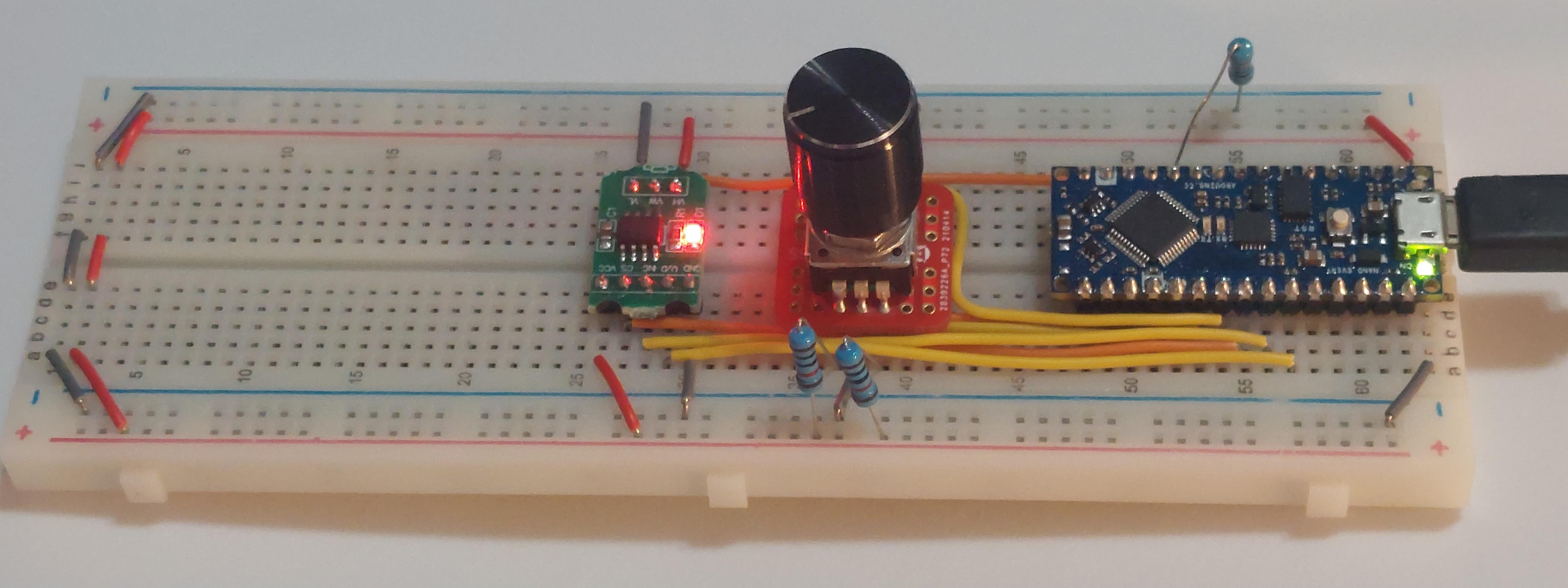
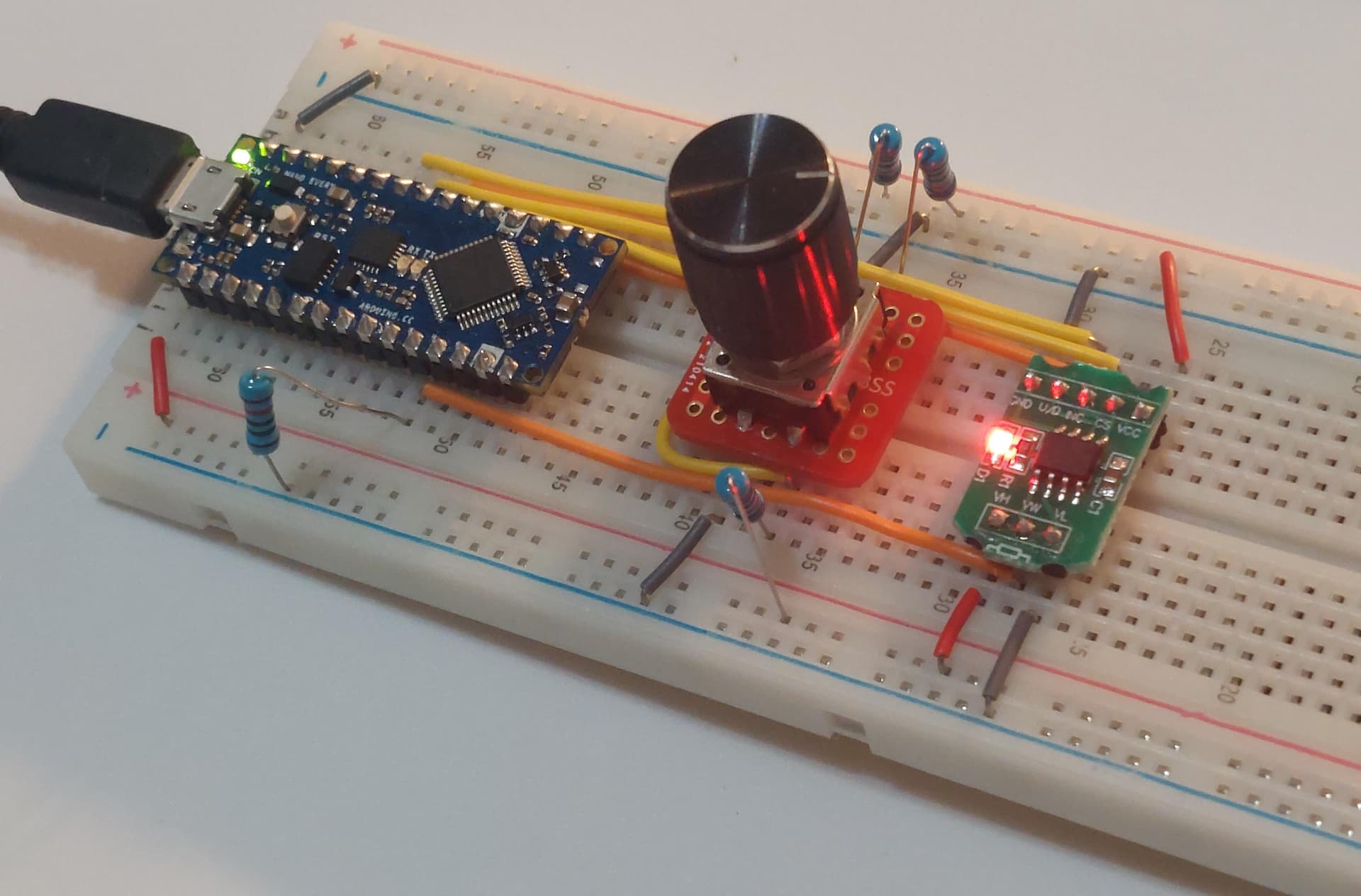
And just in case anyone needs it, here are some pictures of the actual circuit:


Thank you in advance!
-J

What is the final purpose of the electronic potentiometer?

I don't understand these calculations.

I don't see the voltage divider you imply is formed by the X9C103P and R2.

I can't read your picture, can't discern the pin numbers.

Please draw a real schematic, surely showing how the voltage divider is formed.

a7

The purpose is to control the speed of a compressor I have, model GDZH35G. It starts up at about 2k RPM, but can get up to 3.5k if you control the resistance through two specific terminals on the control unit.


I don't plan on always having it at 3.5k RPM, otherwise I would just attach a 1.5k ohm resistor there. But I would like to be able to control it via Arduino (Im testing this out on a Nano Every, but I have a Mega if the need arises), hence the digital resistor.
The problem is that it will shut off if the resistance gets too high. Which is why It would be nice to be able to monitor it (though I'm working on being able to determine the the RPM via some other means - eg: the current being consumed).

P.S. I know these X9C IC's aren't at all the most accurate things (tolerance of ~30%), but I'm just using them to get the logic/code written out. Im looking at some IC's with a more appropriate resistance and much better tolerance on Digikey.

Yeah, its a hell of a mess. But basically its built off of this simple tutorial: How to Make an Arduino Ohm Meter, Which works fantastically, but then when I switch out the "unknown resistor" with the output of the X9C103P, that's when I start getting the crazy high readings.
The relevant parts of the "diagram" I posted above are the R1 resistor (the "known" resistance) which goes from ground to analog pin 7, and the X9C103 (the "unknown" resistance) which also connects to analog 7 (via the orange wire coming out the bottom of the X9C breakout board)

Does that help at all?..

I'm surprised that the encoder seems to work. The above is not the recommended way to call attachInterrupt().

Also, any variables shared between the main program and an interrupt routine should be declared volatile.

That would tell me to focus on the X9C. What to you see when you run the library example programs?

I should be using digitalPinToInterrupt(), right? That is interesting... Now im surprised as well.

Got it. I have a lot to learn - Totally new to C++, I've always done interpreted languages like JS, Python, Perl, Ruby, PHP, etc. So im new to a lot of the stuff that's unique to languages like C/C++.

That's what I thought too, but I tried out several demos, and even compared it with other X9C IC's I have and it seems to work as it should.

Ill see if attaching my multimeter to it will give a reading, I thought that since its on an active circuit, it won't read a resistance, but maybe if I disconnect it and just hook up the multimeter between the wiper and the low terminal it will.

Definitely. However, as the reference page notes, calling attachInterrupt with a pin number is allowed for a few processors. Maybe those few include the Every.

Yeah, That's what I saw as well.

But anyways, guess what guys... I fixed it.

While it was running, I removed the ground pin from VL on the digipot so I could attach the multimeter, and the output in the serial console of Arduino started to show exactly what I would expect. lol. I guess I should be using this more as a rheostat than a potentiometer (If I'm understanding the two accurately)

Thanks for the report. And before, for the extra information, which I may ever read closely.

A regular schematic would have shown plainly the error in your thinking, and thus wiring, if I understand what happened.

A rheostat indeed would be a way to think about the roll of the digipot. The data sheet may be explicit about the wiring of the wiper to the unused end of what would otherwise be a potentiometer.

a7

Yeah, I actually tried making the schematic in a few different web apps (eg: tinker cad, and something else), but they didn't have the Arduino Nano Every, and some of them didn't have basic rotary encoders (at least not that I could find). I got impatient and reverted to what I use for other diagrams - Draw.io. I know it's not the best, but I figured it would work.

Ill try to find something better in the future.

Agreed. Right when I unplugged it and saw the resistance go to the expected values, I remembered the difference between potentiometers and rheostats - Pots control voltage, rheostats control current, and if you look at the diagram on the compressor, they correlate the resistance to amps, as in current. I should have realized that before >_< Oh well, lesson learned.

There is another thing to consider:

The datasheet

says maximum current 1 mA. I have doubts that the compressor-rpm-control-circuit will be humble enough to use less than 1 mA.

Have you ever measured the current at lowest possible and highest possible rpm?

Yeah, I checked that a while ago and I remember it wasn't very high, but i'll check again tomorrow just to be sure.

It's important to know that the connection that I need to control the resistance/amperage isn't at all the connection that is used to power the compressor motor. Its actually on the thermostat that's used to control the temperature if it's getting too hot or running too long. But you can override it with a resistor (or rheostat).
In the image below, the thermostat line is in red (with the variable resistor at the red arrow), and the 12v power is in the top (green) outline.

Obviously it's possible that the leads just connect inside the control unit and the thermostat just controls it directly by changing the resistance, but I would think that if that was the case, a lower resistance would result in a faster RPM, but it's the other way around. I think they kinda just use the resistance as an indicator to where the RPM's should be set to (almost like a user input), but I could absolutely be wrong on that.

P.S., You can see me testing the control using a potentiometer here: Compressor test - Album on Imgur
This thing is pretty neat, it also will report what type of failure it's encountered by flashing an LED, which Ill just connect to to check for the signals. I already have that part all scripted out (which I had a great deal of help with that in a separate thread: Having issues storing volatile pin variable in singleton with method attached to CHANGE interrupt - #20 by jhyland87).

I realized I never posted a video result of the changes implemented after making this thread. If anyone wants to check out a video of it, it's pretty neat. Works surprisingly well.

I guess I shouldn't call it a "final" result, as I actually need to switch the Arduino and multimeter around so the multimeter gets higher resistance (because of how the control unit works, higher resistance = higher rpm's).
I just switched the two around, and while it does work, for some reason its much less accurate. So I'm going to use a INA219 current sensor to monitor the current/resistance and probably create a feedback loop so instead of setting the digipot to a specific desired wiper point, it will just trigger up/down and monitor the output from the INA219.
Additionally, depending on how noisy the output is, I may have to create some logic using the Running Average library.

How do you keep the pot (compressor) terminals within 8volt of Arduino ground.

You can't just connect a digital pot to an electrically 'floating' other device.
Leo..

Read up through the posts, the pot (or rheostat, I guess) hooks up to the thermostat leads, not to the 12v power leads directly. You can control the speed of the pump/compressor by controlling the amps between the C (control) and T (thermostat) terminals.

I measured the amps on the C/T terminals while it was running, and it only got up to 5.11mA, which is pretty manageable. But as someone pointed out above, the digipots im using can't really take that load, so I'll likely use a different type. I ordered a couple different types from Digikey to try out. One of which is the AD5122A, which goes up to just 10k ohms, 8% tolerance and 6 mA wiper current.

Current is not the only problem.
Did you connect compressor battery negative to Arduino ground (can't just leave things floating),
and what are the voltages between thermostat points and ground, with thermostat on and off.
Leo..

I haven't hooked this up to the arduino yet, since I know the DigiPot I have isn't rated for it. But I do plan on having the grounds connected.
Ill get those values for you tomorrow. Thanks!

Hey @Wawa , I got the AD5122A in and tested it out. And after thinking about it a little more and looking at the diagrams, I don't think it needs a common ground. Both digipots (X9C and AD5122A) seem to have the L/W/H pins electrically isolated.
You can see here for the AD5122A (datasheet) that the L/H pins (labeled as A and B) aren't hooked up to ground at all:
AD5122-5142-fbl

Additionally, when I got this running, I hooked up a multimeter to the A/W and B/W pins and saw a resistance (between 0 and 10k), which is exactly what it outputs. I know you can't really check the resistance on a live circuit that easily (usually have to get the amps and use ohms law, as far as I know), so from the point of view from the compressor, seeing a 1.5k resistance from a resistor, a potentiometer, or the A/W pins from this digipot are all the same.

I did try it out, and while it wasn't as responsive as I was hoping for (but I think I just didn't let the compressor warm up, takes 2 minutes I think), it seemed to work ok. Didn't fry the IC and I could see a noticeable change in the amps from the desktop power supply (the IC was powered via the Arduino which was running from a USB cable on my laptop, so no common ground).

I did take a video, but its apparently too long for Imgur to take :-/

How else are you able to keep the pot terminals within supply/GND of the chip.
In the table of the datasheet...
Terminal Voltage Range: min VSS, max VDD.

Make sure you have spares handy.
Leo..