I can communicate with this controller, using a PC, a cable "USB A (RS485)-to- Ethernet" that connects the PC (USB A side) to the controller (Ethernet side), and I can read/write the controller registers using a Python script.
My first question is: how do I connect the Arduino to the controller? Do I need a converter board, or just 2 GPIOs (besides GND and VCC) that I can connect to the USB-A side of the cable that I have? The cable should already have a converter inside.
As for the Arduino code, I assume I need to send messages using the ModbusMaster library, but I am not 100% sure
Are you sure that's an ethernet connection? The manual on the web page you linked to seems to show an RJ45 connector along with the pins used for RS485 comms.
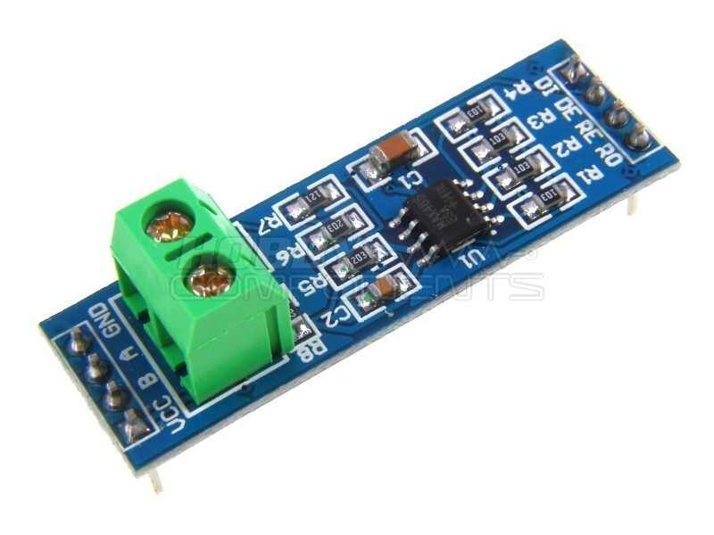
Forget the cable you have that you use with your PC. In order to use the Modbus protocol with a Nano, you need a simple RS485 module like this one:
You then setup a software serial port on your Nano (don't use the hardware serial port) and connect the pins designated for Tx and Rx to the DI and RO pins on your RS485 module. The RE & DE pins on the module are generally joined together and connected to a 3rd pin on the Nano to control the data direction (Tx or Rx) of the MAX485 chip. The VCC and GND pins go to +5V and 0V on your Nano.
Thank you for your quick reply. Yes, that's an RJ45 to be correct.
All clear, just one more question. To connect the RS485 to the controller it looks like I need to short every 2 pins: so 1 and 2 to VCC, 3 and 4 will go to pin B and so on?
My interpretation of that is that the pairs of pins are internally connected. You don't need to do any "shorting" in your cable. Just use pins 3 (or 4), 5 (or 6) and 7 (or 8) and connect them to the RS485 module.